Part Number: TXE8124-Q1
Other Parts Discussed in Thread: TXE8148, TXE8116, TXE8124
Tool/software:
FAQ: Logic and Voltage Translation > SPI I/O Expanders >> Current FAQ
This FAQ describes 6 key spec's for I/O expanders.
These specs include:
- VOH = Output HIGH Voltage
- VOL = Output LOW Voltage
- IOH = Output HIGH Current (source)
- IOL = Output LOW Current (sink)
- ICC(GND) = continuous current through GND
- ICC(VCC) = continuous current through VCC
These electrical specs apply to both I2C and SPI I/O expanders from Texas Instruments. For this example, we will look at TXE8124-Q1
VOH / VOL / IOH / IOL:
The general output structure of the TXE81xx looks as the following:
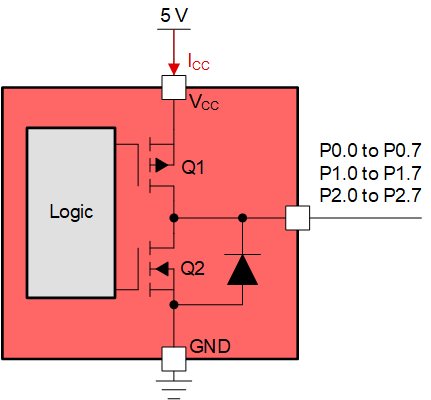
Q1 and Q2 make up the push-pull output structure of the I/O expander. There is an ESD protection diode on the I/O that points from GND to the I/O pin. Q2 is an n-type MOSFET while Q1 is a p-type MOSFET. Both transistors are used to create the high and low logic outputs out to the I/O pins P0.0 - P2.7.
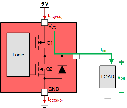
For example, when driving an output HIGH, Q1 is enabled while Q2 is disabled. Q1 pushes current out of the pin by driving the pin towards VCC. VOH is the output HIGH voltage while IOH is the output HIGH current being sourced.
Conversely, when driving an output LOW, Q2 is enabled while Q1 is disabled. Q2 pulls current out of the LOAD by driving the I/O pin towards GND. VOL is the output LOW voltage while IOL is the output LOW current being sank.
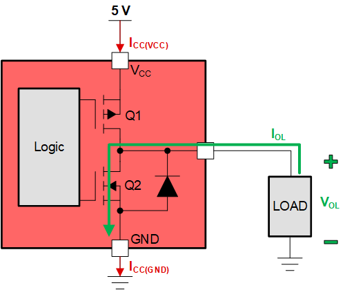
This is the "push/pull" circuit where current is being pushed out or pulled into the TXE81xx I/O expander. The type of load being driven will determine the output voltage and output current seen at the I/O pin. See the electrical characteristics from the datasheet.

P port is highlighted for I/O pins P0.0 - P2.7.
This table shows the maximum and minimum voltages seen for VOH or VOL. The push-pull driver is characterized by these numbers. For example, when VCC = 5.5 V, you can expect your output voltage VOH to be at least 4.95 V when sourcing 8 mA of current (IOH) out of the pin. In theory, the pFET driver has an equivalent drive strength resistance of at least R = (5.5 V - 4.95 V) / 8 mA = 68.75 ohms. When an output logic HIGH is asserted on the I/O pin, it is effectively connecting a pull-up resistance of 68.75 ohms through the pFET driver.
When reading the table for VOL, you can expect a VOL(max) = 0.22 V when VCC = 1.65 V, and the TXE is sinking 4 mA of current (IOL).
The SPI data output SDO also has driver characteristics because it is also a push-pull driver. SDO drives data back to the MCU with these driver characteristics of VOH and VOL.
ICC(GND) and ICC(VCC) - Abs. Max Specifications:
The absolute maximum specifications are found in section 5.1 - Absolute Maximum Ratings in the datasheet.
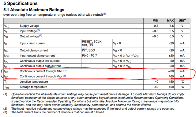
The high-lighted specs are ICC - continuous current through GND, and ICC - continuous current through VCC. These spec's are critical to consider because I/O expanders can have many pins configured to OUTPUT where several loads are being driven at a single time.
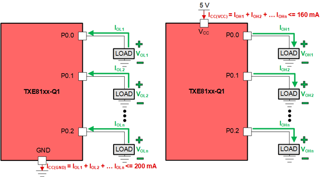
The examples above was showing a single I/O pin driving an output and sinking/sourcing a current through a load. When using TXE8116, TXE8124, or TXE8148, there can be 16 / 24 / 48 outputs simultaneously driving a load. If these total currents exceed the absolute maximum ratings for VCC or GND, potential damage may occur to the device.
Below is an example of the additive current sink and source for driving several outputs. Consider that the I/O expander has a total current budget of which all the I/O's configured as output contribute to.