This thread has been locked.

If you have a related question, please click the "Ask a related question" button in the top right corner. The newly created question will be automatically linked to this question.

DP83848Q-Q1: ET1100 with DP83848Q-Q1 after replacing TLK110 - EtherCAT problems

Part Number: DP83848Q-Q1
Other Parts Discussed in Thread: TLK110,

Hello,

we have replaced the Ethernet PHY TLK110 with DP83848Q-Q1 in an existing design due to part obsolescence and are having issues with the EtherCAT communication, which we are currently troubleshooting.

We also replaced the processor in our application (MPC5534MVZ80 --> SPC564A80B4CFA) and had tests done with the new processor but still old PHY TLK110, where no EtherCAT problems occurred, which leads us to the conclusion that the issues are caused by the PHY.

Our design has 3x Ethernet ports and the PCB is used in two configurations regarding the ET1100 communication, that are differentiated via a solder bridge and two different software configurations (flash content) for the ET1100. The two configurations regarding ET1100 <-> Processor communication are:

  • 3x Ethernet with SPI interface
  • 2x Ethernet with MC interface

Due to these two versions, the third PHY is connected to the ET1100 via a bus switch and the MII disconnected in the 2x Ethernet version.

The situation is somehow latched with Power-On of our PCB - if the PCB "decides" not to work on power on, nothing will help (e.g. restart of our EtherCAT master) but a (or some more) power cycle(s) to our PCB, which may lead to a working behavior.

Before replacing the PHY we were not facing such issues plus we do have a design with 1x Ethernet, where the same "new" PHY does not bring any trouble with the ET1100 / EtherCAT communication. 

Measures that were taken already:

  • using PHY address offset 16 for ET1100 and setting the PHY addresses to 16, 17, 18
  • setting TX delay on the ET1100 to 20 ns, as we faced differing timing on the new PHY (25 MHz are coming from the ET1100 that has a crystal attached
  • added Pulldown 2k2 at PHY X1 clock input as recommended in ET1100 PHY selection guide
  • extended processor reset time to 3 seconds - ET1100 will perform its own Power-On reset and is connected directly to all 3 PHYs (--> PHYs and ET1100 will exit reset state earlier than our processor). We had the feeling that this improved the situation, but we still did not solve the issue
    • --> PHYs are reset without any delay directly by the ET1100
  • activated enhanced link detection in the ET1100 config

After reading through datasheets, PHY selection guide etc. I came up with buzzwords:

  • stable input clock at X1 of the PHY for time xxx and how to maintain this
  • may an extended delay to PHYs AND/OR ET1100 help?
  • may there be problems with enhanced link detection while having the PHY address offset of 16?

Since we are running out of ideas I am kindly asking you to review our design and hopefully point uns towards the design mistake that we seem to be overlooking.

I would like to share our design files (schematic and layout), but cannot do so publicly.

Best Regards

Patrick


  • Hi Patrick, 

    Please accept my friendship request. You can private message me the schematic/layout for review. 
    What is the exact issue you are facing? Is it the link issue, or is there packet loss during EtherCAT communication? Is it the PHY power-up issue?
    We have not heard any issue caused by PHY addressing. 
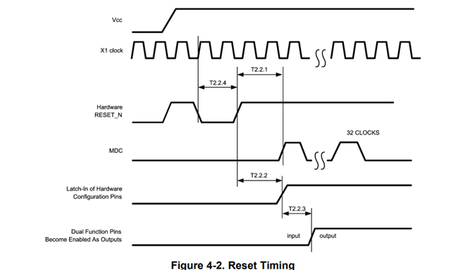
    Could you verify that the PHY reset timing follows the below diagram?


    Also, we recommend the PHY to have a stable XI clock before being powered on ideally. If not, the second reset may be needed. Have you tried resetting the PHY after the PHY fully turns on?


    Lastly, if you could provide us a simple block diagram of the connection between ET1100 and the PHYs, that would be very helpful understanding your problem. 

    Please let me know. 

    Best,
    J

  • Hi J,

    thanks for your answer. I'll send over the Files via PM, but hopefully we can solve the issue in this "public place".

    For your questions (link issue, lost packet loss etc.) I am unfortunately not yet ready to answer, since my colleague dealing with the software part has not come to detailed investigations yet and I am "only the hardware guy". We're on the issue and I'll give an update on my colleagues results asap.

    Please find attached a block diagram, I hope I did not miss out any detail.

    BLOCK_DIAGRAM_ET1100_PHY_2025-11-11_UPLOAD.pdf

    I'll now investigate the X1 clock timing vs. supply voltage and the hardware reset signal with an oscilloscope.

    One question for my understanding - If we had an issue with unstable X1 clock on startup:

    - would it cure the issue if we placed a reset controller between ET1100 and PHY (instead of the 0 Ohm Resistor) that keeps the PHY's Reset input low for just some more time

    OR

    would we need an acutal "second reset pulse"?

    PHYs and ET1100 are supplied via the same 3,3V rail, so unstable clock on startup is likely - ET1100 is the clock source.

    Best Regards

    Patrick

  • Here we can see the obvious:Since ET1100 and PHY share the same 3,3V supply, the input clock at PHY X1 is starting to oscillate some time later (about 90 ms later) after the supply voltage has risen.

    Here is another screenshot with Clock at PHY X1 vs. Reset signal that the ET1100 sends to the PHYs - Reset is released approx. 80ms after the clock starts oscillating (due to lack of hands I could only do 2 signals at one time):

    Is it OK the way it is or shall measures be taken?

    Shall we either:

    - extend the RESET duration for the PHY OR

    - fire another RESET after this procedure?

    --> The first option would be the easier way for us.

    Do you maybe have a suggestion (schematic) on how to solve the issue?

    Best Regards

    Patrick

  • Hi Patrick, 

    Thank you for the detailed response. So, if I am understanding this correctly, the PHY is not powering up some time? 

    The datasheet states that the XI clock has to be stable for at least 167ms before the device is powered up. This could be the reason why the PHY is not starting correctly. 


    For our newer part that may have the similar POR circuitry, second reset pulse after all signals are loaded has been reported to solve this issue. Unfortunately, extending the reset signal is not known to solve this issue. 

    Otherwise, the PHY will have to be powered up after ET1100 is powered and provides XI clock to the PHY. 

    Could you try these solutions?

    Best,
    J

  • Hi J,

    yes, the PHYs are not powered up somewhat delayed, we are supplying them with the same 3,3V rail as the ET1100 and unfortunately there are no 0 Ohm resistors etc in the layout that would allow us to to adjust this, e.g. with a second voltage regulator that comes up later.

    As of now the only option for us is do play with the reset. We'll include a reset controller (TPS3808G33DBVR) with a manual reset button for test purposes, maybe we'll find some processor GPIO that may automate this for our prototypes.

    I'll keep you updated.

    Best Regards

    Patrick

  • Hi Patrick, 

    Please keep me updated. 

    Best,
    J

  • Hi J,

    my colleague in the SW department was on sick leave, thus we could not proceed.

    We managed to install the reset controller that gets its trigger signal right after our processor's initialization sequence. We are resetting ET1100 and PHYs all together - additionally to the inital reset that is initiated by the ET1100.

    The reset pulse to ET1100 and PHYs lasts about 6 ms an is shot about 4,4 seconds after power on (rising edge on 3,3 Volts supply).

    I am including 2 oscillosope screenshots.

    The additional reset does not bring any improvement.

    Furthermore we found out that the problem is directly related with the third port - the one whose MII is routed through the bus switch. We made a test setup with 6 prototypes and my colleague used low-level tools to read out EtherCAT slave info, counter values etc. with no issues, as long as we only use first and second port.

    As soon as we use the third port, to make a connection between the prototypes somewhere, we have two symptoms:

    1. (>95 % of the cases): the whole communication is starting to fail and the low-level tool is no longer able to detect any slave.

    2. The third Port is somewhat "dead" - its link LED is not illuminated and devices connected via this faulty port are not reachable, the rest is working just fine.

    So does not seem to be directly caused by the PHY, but by its connection in our "third port case".

    Do you maybe have an idea?

    - Can propagation delays through the bus switch cause trouble?

    - May we have a layout issue?

    - ...

    Best Regards

    Patrick

  • Hi Patrick, 

    It is unfortunate to hear that the second reset did not resolve the issue. 

    Thank you for the additional information on the third port. 

    So, all six prototypes are showing the same issue with the third port? 

    - Can propagation delays through the bus switch cause trouble?

    This should not be an issue for the link LED to be illuminated. The link LED indicates that there is valid link on MDI side regardless of its connection to the MAC. However, the communication may not still work. 

    In the case the communication fails, is there a link on the PHY? If so, what is the register read of 14h and 15h? This register holds data for false carrier sense and receive error counts of the PHY on the MDI side. It will track any symbol errors. 


    I took a look at the layout, and the layout is definitely not the most optimal layout. However, I doubt that would cause link failure on other ports unless there is a ground short but I doubt this is the case since all three ports have the same layout. 

    If it is possible, could you measure the MDI signal on the third port by probing the transformer on the third port? I want to see if there is any link pulse, or if there is a link, any standard signal being transmitted. With this, we can rule out if there is a connection issue on the port. 

    Please let me know. 

    Best,

    J

  • Hi J,

    please excuse the delay.

    We did some further investigations on the issue that made us step back from investigating the MDI signalling:

    My SW colleague created a debug routine that reads and displays some of the ET1100's registers (from our processor's side), one of them is the POR (Power on register) at address 0x0E00 / 0x0E00, where the ET1100's read strap configuration is stored.

    After some power cycling we found that the ET1100's strap configuration in some cases goes wrong, especially when the PCB is cold. PHY strapping ist also going wrong in some cases. Here are some of the signals I saw affection on (not a complete list of what might go wrong - I am convinced that more signals may be affected):

    ET1100 Strap pin PHY signal Comment
    C25_ENA PHY0_TX(0) examined by reading ET1100 POR
    C25_SH[1] PHY0_TX(3) examined by reading ET1100 POR
    C25_SH[0] PHY0_TX(2) examined by reading ET1100 POR
    none PHY0_AN0/LED_LINK examined by oscilloscope
    none - not connected to ET1100 CRS/CRS_DV/LED_CFG

    examined by oscilloscope

    causes flashing LINK LED with no network connected

    My conclusion is, that the PHY does - although e.g. the TX signals are supposed to be INPUTS on the PHY - be driven to some (random) state after power-on, before the 25 MHz are present. 

    This is due to our violation of the rule "clock X1 must be stable >167 ms at power up" that is hidden in the notes of T2.1.1 / T2.1.2.

    We will include an additional crystal oscillator that ist getting powered before the PHY and ET1100 to maintain the 167 ms X1 clock criterion and make further investigations.

    Long talk short - the DP83848 requires power sequencing for the X1 clock supply.

    Here is a sketch on our approach - do you have any concerns in doing so?

    We want to avoid the delayed Power ON to the PHYs, since:

    - we do not have an elegant option on our prototypes to do so, since the PHYs are lacking 0 Ohm resistors in the supply lines

    - we fear that the PHYs behavior in unpowered state could also affect the ET1100 strapping in an even more undocumented manner

    Best Regards

    Patrick

  • Hi Patrick,

    US office is closed for Thanksgiving. i will review and get back to you next Monday Dallas time.

    Best,

    J

  • Hi J,

    well, Happy Thanksgiving!

    In addition I want to add some thoughts I came up with.

    PHY operation with its own crystal to X1, X2:

    If we were using the PHY with its own crystal, the X1 stable for 167 ms before power up  criterion cannot be maintained, since the crystal will just start to oscillate with or shortly after the PHY's power-up.

    Question:

    Am I misunderstanding the sentence given in the comments of T2.1.1 and T2.1.2? Is it really true that I need to supply a clock 167 ms BEFORE powering the PHY (what should an unpowered device do with this?)?

    Or does this rather mean something like "stable clock must be available at power up" and the 167 ms are just copy-pasted values for the two timing T2.1.1 and T2.1.2?

    I am struggling to understand this issue vs. the situation when the PHY has its own crystal plus I "refuse" to believe, that power sequencing for clock supply is really neccessary.

    We made a test with another EtherCAT-PCB from which we "stole" the 3,3V CMOS 25 MHz clock signal.

    When manually power sequencing (switch on clock source --> switch on prototype), our PCB refused to show the prior errors, just looking at strap configuration (which is positive). Nevertheless: By connecting this external clock, to the unpowered PCB, our 3,3V rail already rises to about 500-600 mV, which:

    - tells me that we might overload the clock source, since it seems to be parasitically powering the whole 3,3V rail

    - i am afraid will cause side effects like reset behavior issues with other ICs on our PCB.

    Conclusion

    We do not really wish to follow the power sequencing path that i described before.

    Could you please check if it would be suitable if we placed a crystal oscillator that is supplied with the same 3,3V as the PHY and ET1100? The one we found states a stabilization time of 5 ms.

    This would be the "cleanest" and minimally invasive solution to us.

    I drew a sketch on the Power-ON situation in the described case.

    - can the PHY live with a "not yet stable" clock at power-on for 5 ms? (should be similar to the case when the PHY has its own crystal)

    - will the PHY inputs be initalized to high-impedance state, in the moment when the ET1100 reads the strapping (Inputs must not be driven - externally pulling up/down via resistors must work here)? (from what i saw on the oscilloscope, it looks like the first, maybe second rising edge of the X1 clock is already doing the trick)

    Best Regards

    Patrick

  • Hi Patrick, 

    I apologize for the delay. 

    I understand the issue here. Unfortunately, DP83848 is a very old part so the current support for this part is limited to the existing documentation. Therefore, I cannot verify if T2.1.1 and T2.1.2 are copied from each other, or is an arbitrary number that was put to cover certain corner cases in the PHY. 

    I agree that clock with a shorter stabilization time will definitely help and crystals that utilize both XI and XO pins (which would use the PHY's feedback loop to provide clk signal to the PHY) may get away with 167ms requirement since the clk will only stabilize after the PHY is on due to the nature of the feedback loop. 


    - will the PHY inputs be initalized to high-impedance state, in the moment when the ET1100 reads the strapping (Inputs must not be driven - externally pulling up/down via resistors must work here)? (from what i saw on the oscilloscope, it looks like the first, maybe second rising edge of the X1 clock is already doing the trick)

    In this case, the PHY inputs initialize into the internal pull-up/down state if the PHY is in reset mode as mentioned in section 3 of the datasheet:


    Lastly, if it is feasible, we recommend to move to our newer parts like DP83826A which are much better supported from our end. 

    Best,
    J

  • Hi Patrick,

    Has there been any update?

    Best,

    J

  • After a long time of me not responding, J was so kind to unlock the thread again, so that I can write a conclusion on the outcome.

    We were able to rework our prototypes with a crystal oscillator and this solved our problem. Thanks a lot for the support! The issues we were facing were in fact caused by the use of the ET1100’s CLK25OUT / CLK25OUT2 pins as the PHY's clock source, combined with the PHY’s – to me a little „strange“ - I/O behaviour.

    So what happened?

    The PHY and the ET1100 both use strapping options, that are latched at power-on:

    The ET1100 starts providing a clock signal directly (80 ns) after its strapping.

    So far, so good – until here everything seems logical and should work, BUT:

    What the PHY datasheet does not explicitly say is that the PHY’s I/Os, including the pins used for strapping (have some „random“ state during power on – as far as I can tell from my measurements, the pins (even the PHY's inputs!!!) are behaving like outputs with a random logic level, until the X1 clock is present and the reset input does not have an effect on this (expected behaviour would rather be: Reset active --> high-Z state on the I/Os). This is affecting both the ET1100 strap options on the MII interfaces of port 0, 1 and 2, as well as the PHY’s own strapping pins in a non-reproducable way. This leads to the circuit latching into some error state at power-on. In combination with the ET1100 this even led to situations, where the PHY was not even supplied with 25 MHz at X1 because it had overwritten the ET1100's strap pin (C25_ENA, shared with TX_D(0)[0]) enabling the clock output.

    How to solve/avoid?

    When using ET1100 in combination with DP83848, do not use the ET1100 as clock source for the PHYuse a crystal oscillator as a shared clock source instead, that is powered on together with ET1100 and PHY, so that the clock is available before strapping starts.

    A power sequencing - as I wrote earlier - is not neccessary and actually does not make sense (parasitic supply via I/O lines etc.)

    This would, next to the ET1100, also apply to all other clock sources that are not beginning to oscillate right after power-on.

    Since I read through some other TI PHYs' datasheets (e.g. DP83826A as recommended by J), it appears to me, that they share this requirement. My recommendation is:

    When there is the X1 clock mentioned in the context of power up timing, use a crystal oscillator for clock supply (for example it was not mentioned for the TLK110, that we were using before & had no problems with)

    I am attaching a sketch on the clock supply as we have done it (and how not to do it).

    do&don't for PHY X1 clock supply

    Best Regards

    Patrick