This thread has been locked.

If you have a related question, please click the "Ask a related question" button in the top right corner. The newly created question will be automatically linked to this question.

DS90UB960-Q1: How to change I2C speed on UB960+UB953

Part Number: DS90UB960-Q1
Other Parts Discussed in Thread: ALP

Hi Ti team, 

We want to increase the communication rate of the I2C link. And tried to add these commond:

board.WriteI2C(devAddr,0x02,0x3E) #Enable Proxy

board.WriteI2C(devAddr,0x0A,0x13)
board.WriteI2C(devAddr,0x0B,0x25)
board.WriteI2C(serAlias[i],0x0B,0x13)
board.WriteI2C(serAlias[i],0x0C,0x26)

But it seems to have affected the accuracy of communication. 

So you can help confirm and inform us of the correct way to configure it?

We want to use fast and also fast-plus I2C MODE, can you give the two configuration to us?

Below is the configuration we use now:


# Fill in I2C addresses and aliases
devAddr = 0x7A # 960 deserializer 8-bit I2C address
serAddr = [0x30,0x30,0x30,0x30] # 953 serializer 8-bit I2C addresses connected to 960 RX port0, port1, port2, port3
serAlias = [0x1A,0x2A,0x3A,0x4A] # 8-bit I2C aliases to read/write serializers connected to 960 RX port0, port1, port2, port3
imgAddr = [0x20,0x20,0x20,0x20] # imager 8-bit I2C addresses connected to 960 RX port0, port1, port2, port3
imgAlias = [0x20,0x22,0x24,0x26] # 8-bit I2C aliases to read/write imagers connected to 960 RX port0, port1, port2, port3
ispAddr = [0x78,0x78,0x78,0x78] # ISP 8-bit I2C addresses connected to 960 RX port0, port1, port2, port3
ispAlias = [0x40,0x42,0x44,0x46] # 8-bit I2C aliases to read/write ISPs connected to 960 RX port0, port1, port2, port3

import time

    board.WriteI2C(devAddr,0x02,0x3E) #Enable Proxy
    
for i in range(0,4):
    if i==0:
        board.WriteI2C(devAddr,0x4C,0x01) # select RX port 0
    elif i==1: 
        board.WriteI2C(devAddr,0x4C,0x12) # select RX port 1
    elif i==2:
        board.WriteI2C(devAddr,0x4C,0x24) # select RX port 2
    elif i==3:
        board.WriteI2C(devAddr,0x4C,0x38) # select RX port 3

    # auto ACK setup
    board.WriteI2C(devAddr,0x5B,serAddr[i]+1) # set serializer address with freeze
    board.WriteI2C(devAddr,0x5C,serAlias[i]+1) # set SER alias and auto ACK
    board.WriteI2C(devAddr,0x58,0x7A) # Enable I2C passthrough with auto ACK, BC rate = 10Mbps

    board.WriteI2C(devAddr,0x0A,0x13)
    board.WriteI2C(devAddr,0x0B,0x25)
    board.WriteI2C(serAlias[i],0x0B,0x13)
    board.WriteI2C(serAlias[i],0x0C,0x26)
    
    # 953 config
    board.WriteI2C(serAlias[i],0x02,0x73) # continuous clock, 4 lanes
    board.WriteI2C(serAlias[i],0xE,0xF0) # disable 935 GPIO0 input and enable output
    board.WriteI2C(serAlias[i],0xD,0x10) # Enable remote Des GPIO0 data on local GPIO0; Pull down gpio2(ISP RESET)
    board.WriteI2C(serAlias[i],0x03,0x12) # MODE override async external clock
    board.WriteI2C(serAlias[i],0x01,0x01) # soft reset
    time.sleep(0.01)

    # I2C address and alias setup
    board.WriteI2C(devAddr,0x58,0x5A) # Disable auto ACK
    board.WriteI2C(devAddr,0x5B,serAddr[i]) # remove freeze
    board.WriteI2C(devAddr,0x5C,serAlias[i]) # disable auto ACK
    board.WriteI2C(devAddr,0x5D,imgAddr[i]) # configure imager address
    board.WriteI2C(devAddr,0x65,imgAlias[i]) # configure imager alias
    board.WriteI2C(devAddr,0x5E,ispAddr[i]) # configure ISP address
    board.WriteI2C(devAddr,0x66,ispAlias[i]) # configure ISP alias

    # 960 config
    board.WriteI2C(devAddr,0x6D,0x7C) # FPD3 CSI-2 input mode
    board.WriteI2C(devAddr,0x6E,0x8A) # map Fsync signal to 953 GPIO0 output
    #board.WriteI2C(devAddr,0x72,0x00) # map VC-ID to 0
    board.WriteI2C(devAddr,0x72,i) # map VC-ID to i

    # FrameSync: 25Hz, 10%/90% duty cycle
    board.WriteI2C(devAddr,0x19,0x05) # FS_HIGH_TIME_1
    board.WriteI2C(devAddr,0x1A,0x34) # FS_HIGH_TIME_0
    board.WriteI2C(devAddr,0x1B,0x2E) # FS_LOW_TIME_1 25fps
    board.WriteI2C(devAddr,0x1C,0xDF) # FS_LOW_TIME_0 25fps
    board.WriteI2C(devAddr,0x18,0x01) # enable internally generated FrameSync

    # Clear error/status
    time.sleep(0.1)
    #board.ReadI2C(devAddr,0x4D)
    #board.ReadI2C(devAddr,0x4E)
    #board.ReadI2C(devAddr,0x55)
    #board.ReadI2C(devAddr,0x56)
    #board.ReadI2C(devAddr,0x7A)
    #board.ReadI2C(devAddr,0x7B)

# CSI Output / Forwarding Config
board.WriteI2C(devAddr,0x1F,0x00) # 1.472 - 1.664Gbps serial rate
board.WriteI2C(devAddr,0x32,0x01) # select CSI port 0
#board.WriteI2C(devAddr,0x34,0x01)
board.WriteI2C(devAddr,0x34,0x31) # enable skew
board.WriteI2C(devAddr,0x33,0x43) # enable skew cal, 4 lanes, continuous clock, enable CSI output
#board.WriteI2C(devAddr,0x21,0x04) # basic sync forwarding on CSI port 0
#board.WriteI2C(devAddr,0x20,0x00) # forward all RX port to CSI port 0, enable forwarding
board.WriteI2C(devAddr,0x21,0x03) # basic sync forwarding on CSI port 0
board.WriteI2C(devAddr,0x20,0x00) # forward all RX port to CSI port 0, enable forwarding



  • Hi Zhang,

    Note that 0x02=0x3E and 960 registers 0x0A/0x0B should only be used if the I2C controller is directly connected to the 953. 0x02=0x3E configures the 960 to act as an I2C controller proxy on its local I2C network and 0x0A/0x0B configure the SCL high/low time on the local network.

    I'm assuming your I2C controller is not directly connected to the 953 and is instead directly connected to the 960. You should not configure 960 registers 0x02, 0x0A, and 0x0B with this setup. Instead, you can configure 953 registers 0x0B and 0x0C to adjust the SCL high/low time on the 953 local I2C network. The 953 will act as an I2C controller proxy on its local network.

    For I2C fast mode, I recommend adding the following lines to the 953 config section of your script.

    • board.WriteI2C(serAlias[i],0x0B,0x13)
    • board.WriteI2C(serAlias[i],0x0C,0x26)

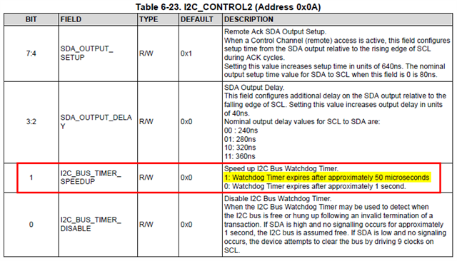
    You can also consider adding the following line to speed up the I2C watchdog timer.

    • board.WriteI2C(serAlias[i],0x0A,0x12)

    Additionally, please note that the I2C controller directly connected the 960 is required to support I2C clock stretching to work with FPD-Link devices.

    Best,

    Lucas

  • Hi Lucas,

    1. Could you provide the UB960+UB953  I2C recommended peripheral circuit for Standard, Fast, Fast-Plus mode?

    2. If our custom used I2C peripheral circuit for UB960 like below, there is a different  pull-up resistor between I2C_CLK and I2C_SDA,  how should we change the configuration of UB960+UB953 to match it?

  • Hi Zhang,

    I'm a bit confused by your schematic. I see the U38 device is a 1:2 mux. Are I2C signals on each side of the mux isolated? Or does the mux directly connect signals on both sides?

    I'm concerned that SDA and SCL may be pulled up in 2 places if the mux directly connects signals. I'm also surprised to see 47k pullup is populated on SDA but not on SCL. Both SDA and SCL should have the same pullup resistance. Only one pullup resistor should be populated on SDA and SCL for the entire I2C bus. 47k is likely too large for an I2C network, typically I2C pullup resistors are in the range 2k-5k.

    Please refer to the following app note for recommendations on what pullup resistance to use.

    8461.I2C Bus Pullup Resistor Calculation.pdf

    Best,

    Lucas

  • Hi Lucas,

    Thanks for your explanation!

    However, this schematic diagram is our customer's own and has already been used.

    Without changing the circuit design, how can we eliminate the impact of unstable I2C communication by modifying the configuration?

  • Hi Zhang,

    Let me look into this further and get back to you later this evening.

    Best,

    Lucas

  • Hi Zhang,

    My recommendation is to depopulate R151-154 and only pullup SDA/SCL with R29 and R35. You can use the Pullup Resistor Calculation app note to determine the optimal resistance value for this application. Typically I2C pullup resistors are in the range 2k-5k.

    Best,

    Lucas

  • Hi Lucas,

    OK, we are trying out your suggestion.

  • Hi Zhang,

    Sounds good, let me know if this resolves the issue or if you need further support.

    Best,

    Lucas

  • Hi Lucas,

    We have discovered a problem that when we configure ISP, sometimes the I2C ACK will lose after UB960, but it can be measured from ISP to UB953. So do you have any idea of this problem?

    Note: there is 1.5K Pullup Resistor on SCL and SDA to 1.8V on UB953, there is 4.7K Pullup Resistor on SCL and SDA  to 1.8V on UB960.

  • Hi Zhang,

    Can you capture an I2C log while the ISP is being configured?

    Can you read 960 registers 0x4D, 0x4E, 0x55, and 0x56 before and after configuring the ISP?

    These data points will help me to understand what could be going wrong.

    Best,

    Lucas

  • Hi Lucas,

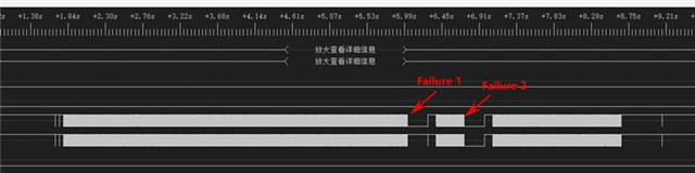
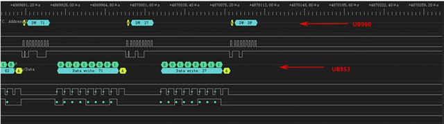
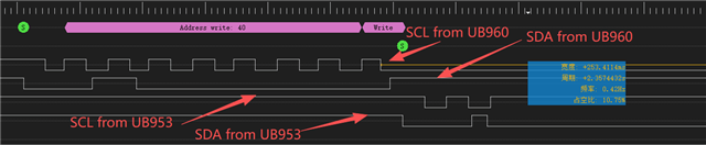
    Below is our I2C waveform,When writing the data 0xDF, UB960 did not transfer it to UB953.

    Below is using 954+953 waveform, it's true:

     .

    These are the registers dump before and after configuring the ISP:

    nv@nv-desktop:~$ i2ctransfer -y -f 30 w1@0x30 0x4d r1
    0xdb
    nv@nv-desktop:~$ i2ctransfer -y -f 30 w1@0x30 0x4d r1
    0xcb
    nv@nv-desktop:~$ i2ctransfer -y -f 30 w1@0x30 0x4d r1
    0xcb
    nv@nv-desktop:~$ i2ctransfer -y -f 30 w1@0x30 0x4e r1
    0x0c
    nv@nv-desktop:~$ i2ctransfer -y -f 30 w1@0x30 0x4e r1
    0x0c
    nv@nv-desktop:~$ i2ctransfer -y -f 30 w1@0x30 0x55 r1
    0x00
    nv@nv-desktop:~$ i2ctransfer -y -f 30 w1@0x30 0x55 r1
    0x00
    nv@nv-desktop:~$ i2ctransfer -y -f 30 w1@0x30 0x56 r1
    0x00
    nv@nv-desktop:~$
    nv@nv-desktop:~$ sudo insmod ap1302_ar0234.ko
    [sudo] password for nv:
    nv@nv-desktop:~$
    nv@nv-desktop:~$ i2ctransfer -y -f 30 w1@0x30 0x4d r1
    0xcb
    nv@nv-desktop:~$ i2ctransfer -y -f 30 w1@0x30 0x4d r1
    0xcb
    nv@nv-desktop:~$ i2ctransfer -y -f 30 w1@0x30 0x4e r1
    0x4d
    nv@nv-desktop:~$ i2ctransfer -y -f 30 w1@0x30 0x4e r1
    0x0c
    nv@nv-desktop:~$ i2ctransfer -y -f 30 w1@0x30 0x4e r1
    0x0c
    nv@nv-desktop:~$ i2ctransfer -y -f 30 w1@0x30 0x55 r1
    0x00
    nv@nv-desktop:~$ i2ctransfer -y -f 30 w1@0x30 0x55 r1
    0x00
    nv@nv-desktop:~$ i2ctransfer -y -f 30 w1@0x30 0x56 r1
    0x00
    nv@nv-desktop:~$ i2ctransfer -y -f 30 w1@0x30 0x56 r1
    0x00
    nv@nv-desktop:~$

  • Hi Lucas,

    Addition comments:

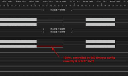
    The hold time of the I2C bus in case of failure is determined by the 960 configuration :BCC_WATCHDOG_TIMER.

    When we configure reg 0x07 val 0x78, the bus release time becomes 120ms

    When BCC_EN_ENH_ERROR is enabled, read BCC_*_ERR status (0x47) after an error occurs

    a. In most cases, there is no mistake

      Bit 7: RESERVED = 0

      Bit 6: RESERVED = 0

      Bit 5: BCC_SEQ_ERROR = 0

      Bit 4: BCC_MASTER_ERR = 0

      Bit 3: BCC_MASTER_TO = 0

      Bit 2: BCC_SLAVE_ERR = 0

      Bit 1: BCC_SLAVE_TO = 0

      Bit 0: BCC_RESP_ERR = 0

    b. Occasionally, a BCC SLAVE TO is set to 1

    Bit 7: RESERVED = 0

      Bit 6: RESERVED = 0

      Bit 5: BCC_SEQ_ERROR = 0

      Bit 4: BCC_MASTER_ERR = 0

      Bit 3: BCC_MASTER_TO = 0

      Bit 2: BCC_SLAVE_ERR = 0

      Bit 1: BCC_SLAVE_TO = 1

      Bit 0: BCC_RESP_ERR = 0

  • Hello,

    The team is out due to a public Holiday in the US. Responses will be delayed until Monday.

    Thank you for your patience

  • Hi Zhang,

    Thank you for your detailed response.

    In your register reads, I see 0x4D=0xCB which indicates a bidirectional control channel error was flagged. I see in register 0x47 that this is a BCC slave timeout flag. I see 0x4E=0x0C which indicates the received CSI line count changed, however I believe this is not relevant since the ISP configuration is not complete.

    I see in your 960 I2C waveform that SCL is held low between byte transactions, before the ACK response is received. This is I2C clock stretching and is expected behavior for remote I2C transactions across the link. The 960 acts as a slave proxy and holds SCL low while the transaction is sent across the link to the 953, which acts as a master proxy and forwards the transaction to the ISP. Once the 960 receives the ACK response, it releases SCL and sends the ACK response back to the SoC.

    In the 953 I2C waveform, both SCL and SDA are held low between byte transactions, after the ACK response is received. This is different from I2C clock stretching and is not normal I2C behavior. I have a few questions to try and understand why SDA/SCL are held low.

    • You mentioned SDA/SCL are pulled up to 1.8V with 1.5k resistors on the camera module. Is the 953 IDX pin correctly strapped for 1.8V I2C voltage?

    • Is the ISP holding the I2C bus low? I recall you mentioned some camera modules will not populate the ISP. Do these modules initialize without any issue?
    • Can you share your configuration code one more time, so I make sure I have the most up to date version? I'd like to review and see if there are any software issues which could lead to the 953 holding the bus low.

    Best,

    Lucas

  • Hi Lucas, 

    We solved the problem of unstable I2C transmission by modifying the back channel rate from 10 Mbps to 50 Mbps.

    Below is the configuretion we now use(I sent route 1 as example): 

        //{0x30,0x02,0x3E}, //Enable Proxy
        {0x30,0xB3,0x00}, // bist config 0
        {0x30,0x4C,0x01}, // select RX port 0
        // auto ACK setup
        {0x30,0x5B,0x31}, // set serializer address with freeze
        {0x30,0x5C,0x1B}, // set SER alias and auto ACK
        {0x30,0x58,0x5E}, // Enable I2C passthrough with auto ACK, BC rate = 50Mbps
        {UB9XX_DELAY, 0x00, 50}, // delay 50 msec
        // 953 configs
        // {0x0D,0x01,0x03}, //reset UB953
        // {UB9XX_DELAY, 0x00, 20}, // delay 20 msec
    #if USE_I2C_FAST_MODE
        {0x0D,0x0B,0x13}, //400Khz i2c speed
        {0x0D,0x0C,0x26},
        {0x0D,0x0A,0x12}, //WD 50ms
    #endif
        //{0x30,0x0A,0x20},
        //{0x30,0x0B,0x31},
        //{0x0D,0x0A,0x12}, // Speed up I2C Bus Watchdog Timer
        {0x0D,0x02,0x73}, // continuous clock, 4 lanes
        {0x0D,0x0E,0xF0}, // disable 935 GPIO0 input and enable output
        {0x0D,0x0D,0x10}, // Enable remote Des GPIO0 data on local GPIO0; Pull down gpio2(ISP RESET)
        {UB9XX_DELAY, 0x00, 50}, //delay 10 msec
        {0x0D,0x0D,0x14}, //reset AP1302
        //{0x0D,0x03,0x12}, // MODE override async external clock
        {0x0D,0x01,0x01}, // soft reset
        {UB9XX_DELAY, 0x00, 50}, //delay 10 msec
        // I2C address and alias setup
        {0x30,0x58,0x5E}, // Disable auto ACK
        {0x30,0x5B,0x30}, // remove freeze
        {0x30,0x5C,0x1A}, // disable auto ACK
        {0x30,0x5D,0xAC}, // configure EEPROM address
        {0x30,0x65,0xA2}, // configure EEPROM alias
        {0x30,0x5E,0x78}, // configure ISP address
        {0x30,0x66,0x40}, // configure ISP alias
        // 960 config
        {0x30,0x6D,0x7C}, // FPD3 CSI-2 input mode
        {0x30,0x6E,0x8A}, // map Fsync signal to 953 GPIO0 output
        {0x30,0x72,0}, // map VC-ID to 0
        // FrameSync: 25Hz, 10%/90% duty cycle
        //{0x30,0x19,0x05}, // FS_HIGH_TIME_1
        //{0x30,0x1A,0x34}, // FS_HIGH_TIME_0
        //{0x30,0x1B,0x2E}, // FS_LOW_TIME_1 25fps
        //{0x30,0x1C,0xDF}, // FS_LOW_TIME_0 25fps
        {0x30,0x19,0x1A}, // FS_HIGH_TIME_1
        {0x30,0x1A,0x04}, // FS_HIGH_TIME_0
        {0x30,0x1B,0xEA}, // FS_LOW_TIME_1 25fps
        {0x30,0x1C,0x5B}, // FS_LOW_TIME_0 25fps
        {0x30,0x18,0x01}, // enable internally generated FrameSync
        {UB9XX_DELAY, 0x00, 100},
        // CSI Output / Forwarding Config
        {0x30,0x1F,0x00}, // 1.472 - 1.664Gbps serial rate
        {0x30,0x32,0x01}, // select CSI port 0
        {0x30,0x34,0x31}, // enable skew
        {0x30,0x33,0x43}, // enable skew cal, 4 lanes, continuous clock, enable CSI output
        {0x30,0x21,0x03}, // basic sync forwarding on CSI port 0
        {0x30,0x20,0x00}, // forward all RX port to CSI port 0, enable forwarding
  • Hello,

    The team is out due to the Holidays. Responses will be delayed from Dec. 24 through Jan. 2.

    Thank you for your patience

  • Hi Zhang,

    Good to hear the issue was resolved by modifying the back channel rate. Note that 10Mbps back channel rate is typically used with async clock mode and 50Mbps back channel rate is typically used with sync clock mode. Let me know if there are any further issues.

    Best,

    Lucas

  • Hi Lucas,

    Do we have any registers on UB960 to refresh data path, in order to eliminate the initial few bad frames.

  • Hi Zhang,

    I'm assuming the first video frame is bad because deserializer output is enabled after the imager starts streaming? Can you try moving imager config after the CSI output/forwarding config section?

    Best,

    Lucas

  • Hi Lucas,

    Yes, we suspect that there might be some issues with the first few frames of the camera.

    I have already put sensor start stream after configure 960+953, But sometimes errors occur when capture image at the beginning, so I want to try refresh datapath of UB960 before  I capture.

  • Hi Zhang,

    There isn't a function to refresh the datapath of the 960.

    What type of errors are reported by the SoC? Can you read the following registers repeatedly after initialization, so I can get a better idea what errors are reported by the 960 and 953?

    • 960: 0x4d, 0x4e, 0x55, 0x56, 0x73-0x76, 0x7a, 0x7b, 0x90-0x97
    • 953: 0x52, 0x55, 0x56, 0x5c-0x64

    Best,

    Lucas

  • Hi Lucas,

    We solved the problem by enable and disable forwarding of RX Port. There is no error from the report.

    The previous issue might have been caused by the fact that the media we used required data to be captured starting from the frame header.So, re-enabling the forwarding of the RX Port can solve this problem.

  • Hi Zhang,

    Good to hear the issue was resolved, thank you for sharing your solution. You could possibly move the register write to enable forwarding after the imager configuration is complete, so you don't have to disable/re-enable forwarding.

    Best,

    Lucas

  • Hi Lucas,

    During the development of my project, I discovered that a specific module had some issues with I2C communication. I wanted to use UB960+ UB953 to identify the cause of the problem. 

    When I compared the values of the registers, I found that some of the registers had differences that were not listed in my datasheet. Could you please explain these registers for me?  For UB953, address from 0x9A to 0xA4.

    Also, can you help to confirm what is the problem with I2C by the register dump?

    Below is the register value:

    UB953:

    0x00: 0x30 0x00 0x73 0x58 0x00 0x03 0x41 0x28 0xfe 0x1e 0x10 0x1c 0x1c 0x14 0xf0 0x00
    0x10: 0x00 0x00 0x00 0x00 0x00 0x20 0x18 0x3c 0x80 0x62 0x62 0x62 0x00 0x00 0x00 0x00
    0x20: 0x00 0x00 0x00 0x00 0x00 0x02 0x00 0x00 0x67 0x33 0x01 0x00 0x00 0x00 0x00 0x00
    0x30: 0x00 0x20 0x09 0x04 0x00 0x10 0x00 0x60 0x00 0x00 0x00 0x00 0x00 0x00 0x00 0x00
    0x40: 0x00 0x00 0x00 0x00 0x00 0x00 0x00 0x00 0x00 0x00 0x00 0x00 0x00 0x00 0x00 0x00
    0x50: 0x20 0xc0 0x45 0x00 0x00 0x00 0x00 0x00 0x07 0x07 0x07 0x00 0x00 0x00 0x00 0x00
    0x60: 0x00 0x00 0x00 0x00 0x00 0x88 0x00 0x00 0x00 0x00 0x00 0x00 0x00 0x00 0x00 0x00
    0x70: 0x00 0x00 0x25 0x00 0x00 0x00 0x00 0x00 0x00 0x00 0xe4 0x00 0x00 0x00 0x00 0x00
    0x80: 0x00 0x00 0x00 0x00 0x00 0x00 0x90 0x00 0x00 0x00 0x00 0x00 0x06 0x00 0x00 0x00
    0x90: 0x32 0xe3 0x64 0x01 0x00 0x00 0x00 0x00 0x00 0x00 0x26 0x22 0x07 0x05 0x03 0x10
    0xa0: 0x00 0x0f 0x0f 0x0d 0x0c 0x10 0x42 0x10 0x10 0x10 0x03 0x01 0x00 0x00 0x00 0x00
    0xb0: 0x04 0x4a 0x3f 0x00 0x00 0x00 0x00 0x00 0x00 0x00 0x00 0x00 0x00 0x00 0x00 0x00
    0xc0: 0x00 0x00 0x00 0x00 0x00 0x00 0x00 0x00 0x00 0x00 0x00 0x00 0x00 0x00 0x00 0x00
    0xd0: 0x00 0x00 0x00 0x00 0x00 0x00 0x00 0x00 0x00 0x00 0x00 0x00 0x00 0x00 0x00 0x00
    0xe0: 0x00 0x00 0x00 0x00 0x00 0x00 0x00 0x00 0x00 0x00 0x00 0x00 0x00 0x00 0x00 0x00
    0xf0: 0x5f 0x55 0x42 0x39 0x35 0x33 0x00 0x00 0x00 0x00 0x00 0x00 0x00 0x00 0x00 0x00

    UB960:

    0x00: 0x60 0x00 0x1e 0x40 0xd0 0x01 0x00 0xfe 0x1c 0x10 0x7a 0x7a 0x0f 0x09 0x20 0xff
    0x10: 0x00 0x00 0x00 0x00 0x00 0x00 0x00 0x00 0x01 0x1a 0x04 0xea 0x5b 0x00 0x04 0x00
    0x20: 0xf0 0x03 0x00 0x00 0x00 0x00 0x00 0x00 0x00 0x00 0x00 0x00 0x00 0x00 0x00 0x00
    0x30: 0x00 0x00 0x01 0x43 0x31 0x00 0x00 0x00 0x00 0x00 0x00 0x00 0x00 0x00 0x00 0x00
    0x40: 0x00 0xa9 0x71 0x01 0x00 0x00 0x60 0x02 0x00 0x00 0x00 0x12 0x01 0x03 0x04 0x64
    0x50: 0x00 0x00 0x00 0x02 0x00 0x00 0x00 0x00 0x5e 0x00 0x00 0x30 0x10 0x20 0x78 0x00
    0x60: 0x00 0x00 0x00 0x00 0x00 0x20 0x40 0x00 0x00 0x00 0x00 0x00 0x00 0x7c 0x8a 0x88
    0x70: 0x2b 0x2c 0x00 0x00 0x00 0x00 0x00 0xc5 0x00 0x01 0x00 0x00 0x20 0x00 0x00 0x00
    0x80: 0x00 0x00 0x00 0x00 0x00 0x00 0x00 0x00 0x00 0x00 0x00 0x00 0x00 0x00 0x00 0x00
    0x90: 0x00 0x00 0x00 0x00 0x00 0x00 0x00 0x00 0x00 0x00 0x00 0x00 0x00 0x00 0x00 0x00
    0xa0: 0x00 0x00 0x00 0x00 0x00 0x1c 0x00 0x00 0x00 0x00 0x00 0x00 0x00 0x00 0x00 0x00
    0xb0: 0x1c 0x3a 0x14 0x08 0x25 0x00 0x18 0x00 0x8c 0x33 0x83 0x74 0x80 0x00 0x00 0x00
    0xc0: 0x00 0x00 0x00 0x00 0x00 0x00 0x00 0x00 0x00 0x00 0x00 0x00 0x00 0x00 0x00 0x00
    0xd0: 0x00 0x43 0x94 0x06 0x60 0xf2 0x00 0x02 0x00 0x00 0x00 0x00 0x00 0x00 0x00 0x00
    0xe0: 0x00 0x00 0x00 0x00 0x00 0x00 0x00 0x00 0x00 0x00 0x00 0x00 0x00 0x00 0x00 0x00
    0xf0: 0x5f 0x55 0x42 0x39 0x36 0x30 0x00 0x00 0x00 0x00 0x00 0x00 0x00 0x00 0x00 0x00

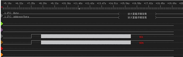
    This is the I2C waveform

  • Hi Zhang,

    Looking back at your code, I believe this is an I2C write to the ISP on the camera module. I see 0x40 is the I2C alias assigned to the ISP connected to RX port 0.

    I see communication between the I2C controller and the 960 is normal. The 0x40 byte is sent normally, then the 960 holds SCL low (clock stretching) while it waits for an ACK/NACK response from the 953. The 953 receives the I2C transaction from the 960 and begins transmitting to the ISP when SCL stops toggling and SDA is held low indefinitely. My initial thoughts are that this is either an issue with the electrical signaling on the I2C lines or an issue with the I2C state machine within the 953.

    953 registers 0x9A-0xA4 are trim registers which vary chip to chip. They are unrelated to I2C or this issue. I reviewed error/status registers in your register dumps and the only error I see flagged is BCC target timeout error in 960 register 0x47[1]. This is a symptom of I2C getting stuck on the camera module, so the 960 never receives an ACK/NACK from the 953 before the watchdog timer expires and a timeout occurs.

    I have a few questions/recommendations to debug this issue.

    • I see you mentioned this issue only occurs on one camera module. Does it happen every time an I2C transaction is sent to the ISP or the imager? Or does it only happen occasionally?
    • Looking back at your I2C design, I believe the camera module uses 1.5k pullups to 1.8V on the I2C bus. Have you verified there aren't any faults with the pullup resistors or supply rails (I2C, 953, ISP) on this camera module?
    • It would be helpful if you can captures a few more waveforms when the issue occurs. I'd like to see if the issue presents itself differently over multiple occurrences.
    • Can you try enabling back channel alarms by writing 953 register 0x1E=0x7E during initialization? Can you share register dumps of 953 and 960 after the issue occurs again? I'd like to check if any back channel alarm conditions are flagged.

    Best,

    Lucas

  • Hi Lucas,


    It not happen every time, but when I I2C transfer fail, it will always fail.The timeout I mentioned is just one case.

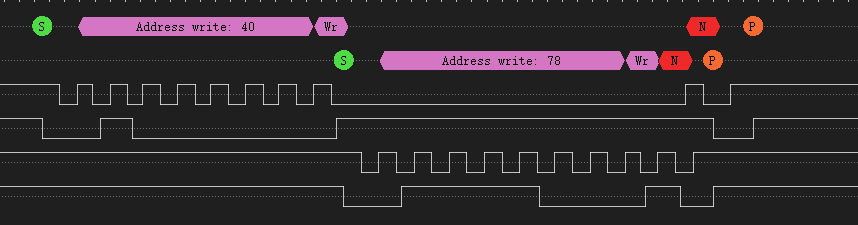
    In addition, there is another more common phenomenon without ACK, as follows:

    I have confirm that module use 1.5K pullups to 1.8V on the I2C bus.

    I will conduct more tests next week.

  • Hi Zhang,

    I understand the issue does not occur on every remote I2C transaction, but once it occurs the I2C bus cannot be recovered without a power cycle?

    I see in this case that the ISP did not pull SDA low after receiving the address byte 0x78, therefore resulting in a NACK response.

    I look forward to reviewing the results of your further testing to gain a better understanding of what's happening here.

    Best,

    Lucas

  • Hi Lucas,

    The two waveform mentioned before are all the failed waveform.

    We have discovered that the stray wires on the I2C signal might also affect communication. Currently, we are trying to identify the problem through hardware soldering.Perhaps some of the chips in this module were not soldered perfectly.

    I will contact you if there are any further developments or other situations.

  • Hi Zhang,

    Thank you for the update. Let me know if the issue is resolved via soldering, or if further support is needed to debug.

    Best,

    Lucas

  • Hi Lucas,

    We are doing test for UB960/UB953 Link Margin, and have some problem to ask you.

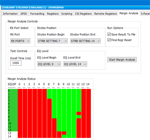
    I use the Analog LaunchPAD and result as below, 

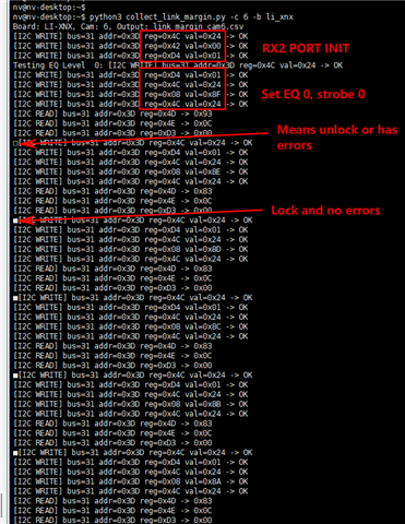
    But when I try to test it by my self, the method and result as below:

    Why is the result so much worse? Is it because the register operation was incorrect? 

    Can you provide the operation about the tool use?

  • Hi Zhang,

    What script are you running for margin analysis? There is a script available within your ALP files (C:\Program Files (x86)\Texas Instruments\Analog LaunchPAD v1.57.0010\PreDefScripts\DS90UB960\ub960_margin_analysis_script). The I2C writes/reads in your screenshot don't seem to match this script.

    Additionally what dwell time are you using? A different dwell time could lead to different results.

    Best,

    Lucas

  • Hi Lucas,

    Yes, we have find the script by your advice and have used it now.

    Do we need to modify the configuration based on the test results of the margin to enable the chip to operate in a better mode, make the channel between UB960 and UB953 more stable, and restore faster?

    If yes, how should we change the registers?

  • Hello Zhang,

    I will be supporting this issue while Lucas is out of office. Right now, the open questions are on the MAP tool. At power-up, the UB960 RX port cycles through a series of EQ and Strobe settings, to eventually settle on values that can establish LOCK onto the incoming serializer signal.

    The MAP script manually sets the EQ and Strobe settings at the RX Port and loops through all possible option for x amount of dwell time. If any errors occur on the link during this dwell time, then the MAP tool marks the specific EQ/Strobe setting as "fail". To get a more accurate result, the dwell time should typically be longer, to have more times to catch errors at the specific EQ/Strobe setting.

    In general, we recommend not modifying any of the EQ/Strobe registers in the UB960 device for the most robust operation.

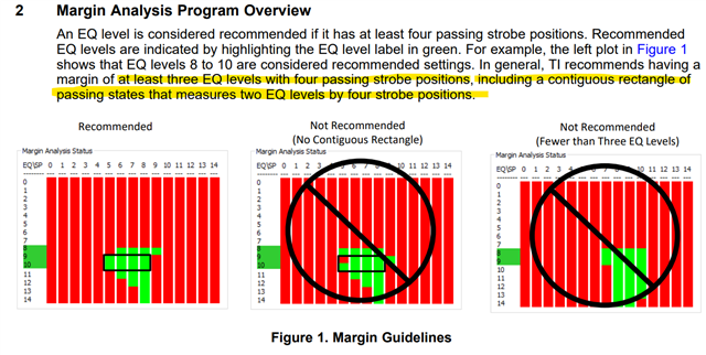
    The general pass criteris for MAP is a continuous square, consisting of PASS results that are 2 EQ levels wide by 4 Strobe Positions long, as indicated in our App Note. There should also generally be 3 rows of passing EQ results.

    https://www.ti.com/lit/ug/snlu243/snlu243.pdf

    Why is the result so much worse? Is it because the register operation was incorrect? 

    Can you provide the operation about the tool use?

    1. Just to double-check, are these your latest MAP results?
      1. It seems like you have 2 levels of pass EQ levels, but not 3.
    2. Did you directly run the MAP Python script that TI provided, or did you make any modifications?
      1. If you would like, you can provide the script you ran and we can double-check it.
    3. If there are no issues with the script, then there is not a software method to expand the link margin. This is mainly related to HW. The next debug step would be to evaluate if the Insertion Loss and Return Loss between your SerDes devices is within the limits defined by TI.

    Best,

    Justin Phan

  • Hi Justin,

    Thanks for your information !

    We have changed the script and got the same result as "Analog LaunchPAD". 

    Now we can get PASS results, and will follow your advice that do not modify the EQ/Strobe registers.

  • Hello Zhang,

    Sounds good. In that case, it seems all open issues have been resolved. I will close this ticket now. Feel free to reach out again if there are additional questions.

    Best,

    Justin Phan