


Part Number: AM26LV32E
Hi all,
Even though the peripheral circuit has not been changed, the waveform is distorted simply by replacing the existing FAB (DLN) with FAB (RFAB).
Send the equivalent circuit, propagation delay, and oscilloscope waveform.
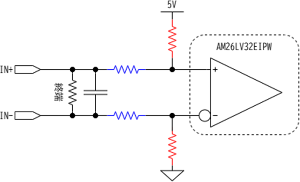
Left: DLN, Right: RFAB
CH1:IN+
CH2:IN-
CH3: A (line receiver non-inverting input)
CH4: B (line receiver inverting input)
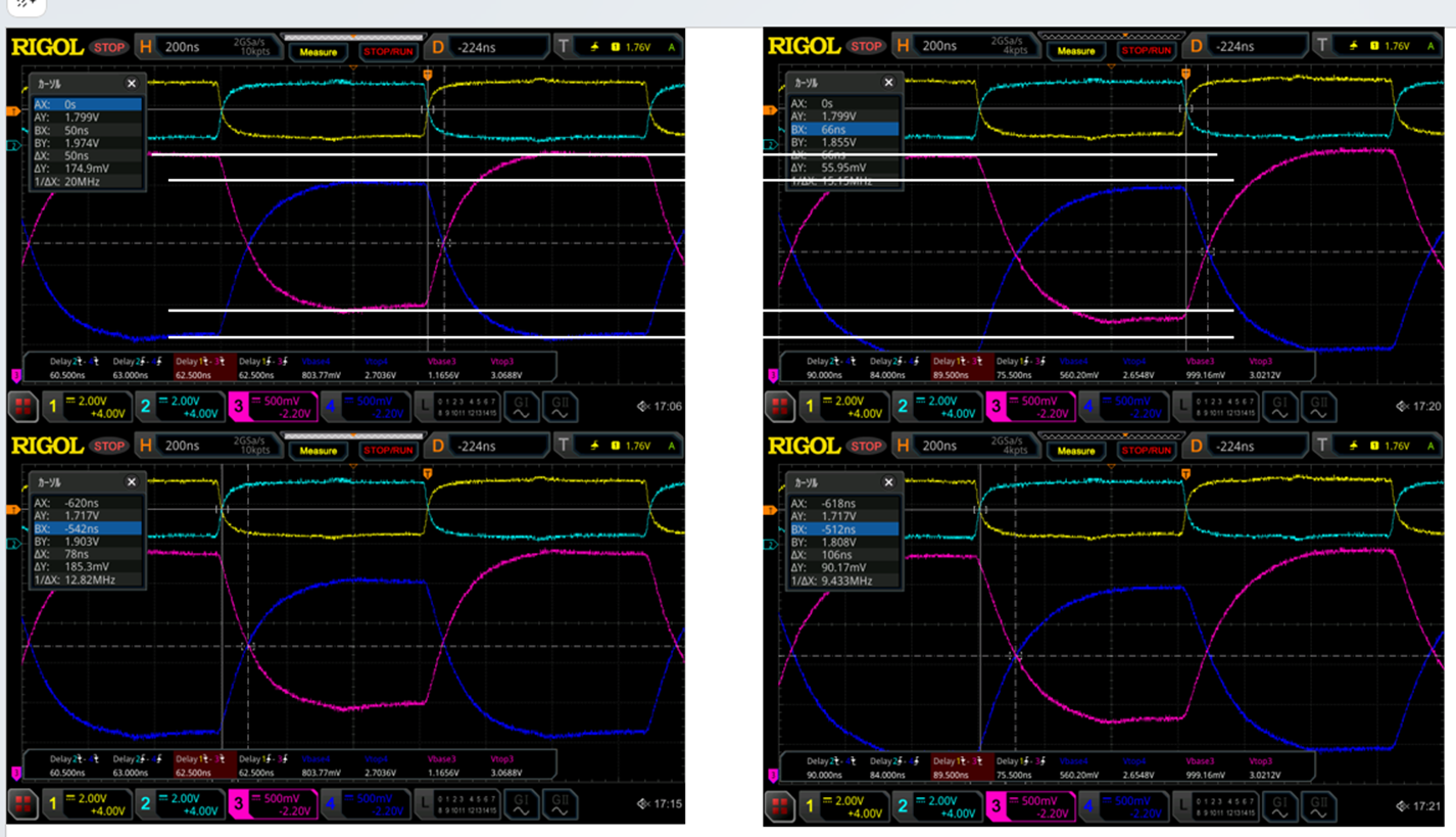
If the signal delay is a problem, I think it is related to the change of capacitance component.
There is Cpd Power dissipation capacitance One channel 150 pF (typ).

1) Is there any difference in Cpd before and after the process? How much difference is there?
2) When the resistance values between Vcc-A/B-GND were measured, the results were different as shown below.
| No. | Measure Point |
Value of resistor | |
| DLN | RFAB | ||
| 1 | Vcc-A | 222k | 130k |
| 2 | B-GND | 222k | 130k |
| 3 | A-GND | 888k | 141k |
| 4 | Vcc-B | 546k | 142k |
Is the measurement result of RFAB reasonable?
If the characteristics of RFAB are reasonable, how wide is the variation of the resistance value?
Best Regards,
Ryusuke
