Part Number: DP83822I
Hi all,
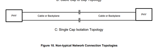
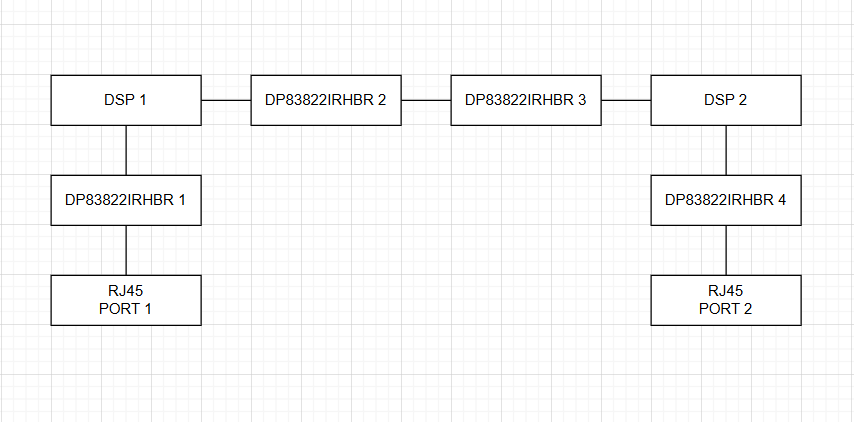
The attached pictures describe the situation the easiest, so please check it out :)
Main question: is it possible? If yes, are there specific HW/FW requirements that are needed to be matched?
Greetings,
Tim
This thread has been locked.
If you have a related question, please click the "Ask a related question" button in the top right corner. The newly created question will be automatically linked to this question.
Part Number: DP83822I
Hi all,
The attached pictures describe the situation the easiest, so please check it out :)
Main question: is it possible? If yes, are there specific HW/FW requirements that are needed to be matched?
Greetings,
Tim

Hi Tim,
DP83822 will support this option.
For connection between two DP83822s, you will have to use transformerless operation with capacitors. More information is in this link: [FAQ] TI Ethernet PHY Capacitive Coupling (Transformerless Operation) and DP83848 Transformerless Operation.
For the driver, you will have to enable two PHYs as separate ethernet ports.
Best,
J
Hi J,
Thank you for the fast reply! I noticed DP83822 not being mentioned in "DP83848 Transformerless Operation.". Are you sure it is possible?
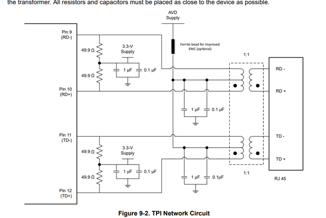
Today I manually added 50ohm pull up on the RD-,RD+,TD-,TD+. (shown in Figure 9-2)

I didn't add the Isolation Caps (as this requires scraping open a line on the PCB). Could you explain why they are needed? Both PHY are run on the same 3.3V, do I still need this?
Greetings,
Tim
Hi Tim,
The document does not mention DP83822 because the document was published before this device was released.
The caps are needed to isolate two PHYs from each other as they both are current mode driver and would drive the current. The caps are there to ensure that the signal is properly driven on both directions.
Best,
J
Hi J,
Today I managed to cut open the trace and insert the capacitors in series. I installed generic 0402 0.1uF caps. It still doesn't work... I was wondering if more specialized caps are needed? (I can imagene that the frequency response of different caps will be different and this will influence the 10 Mbit signals of the PHY)
Greetings,
Tim
I measured signals comparing working status (PHY <-> PORT) and not working (PHY <-> PHY) after this modification. They can be found in attachment.
SafetyDSP EtherCAT Expansion.docx
Also: are there special things required in FW to allow for this Transofrmerless Operation? (Like registers needed to be set)
Greetings,
Tim
One more thing that might cause issues is the way the caps are installed:
This destroys the 50 Ohm impedance routed trace, so probably not the best for difference in phase shifts and reflections. Do you think this should still work?
Greetings,
Tim
Hi Tim,
I don't believe the rework will make the link work unfortunately.
Also, no special FW is needed for transformerless operation.
In addition, are two PHYs linking up, or is there no link at all? If not, could you measure the MDI pin to see if you can probe FLP signal? Also, could you share the schematic so we can verify if the MDI connections are correct?
I also saw the word docx. Do you have waveforms that you can zoom in? I am unsure if that MDI signal is MLT-3 signal. They are supposed to be Vpp = 2.1V with 0V as a reference. How are you measuring this signal?
Best,
J
Hi J,
Do you think soldering the caps directly on the pcb traces (without the extra cables in between the trace and PCB) could work?
LED0 stays high all the time. Tommorow I will measure this MDI pin. Any special things I should keep in mind for interpreting this signal?
I don't think I'm allowed to share the schematics... In between the two PHYs; the RD+ is connected tot TD+ and vice versa.
I did not save the waveforms, as our PICO is not fast enough to properly read the EtherCAT signals. I'm measuring them differntial (math channels on PICO).
Greetings,
Tim
Hi Tim,
Is the probe you are using differential that has 100 ohm termination? It might be more tricky to measure with single ended probes.
if you could draw the MDI connection between two PHYs with the label of which pin going to which pin would be helpful for us to visualize the connection since you cannot share the schematic.
I would say putting the capacitors on top of the trace would be better but because there was no pad to begin with the signal integrity would not be good at all.
Best,
J
Hi Tim,
Thank you for the block diagram. The connection seems to be right.
I am wondering however if the mux supports current mode driver. Could you check if the mux supports current mode driver?
Autonegotiation should be fine enabled.
Best,
J
Hi Tim,
Sounds good.
Is the AVD on DP83822 1.8V or 3.3V, by the way?
If AVD is 1.8V, the pull-up should go to AVD. I just wanted to make sure since our datasheet does not specify this correctly at the moment.
Out of curiosity, is the other PHY connected to the MUX also DP83822?
Lastly, Could you measure FLP signal on the TD_P pin of both DP83822 to see if there is any signal? Also, if you could access the registers, it would be great if you can provide the register dump of both PHYs from 0x00 to 0x1F.
Best,
J
Hi J,
The AVD on DP83822 is 3.3V.
Thank you for letting me know
All PHYs connected to the MUX are DP83822. The reason for the mux is to either (a) send the EtherCAT straight out through RJ45 port OR (b) to send the EtherCAT loop through a sattelite board first and then to the RJ45 port.
Is that possible using the PICO 4000 series?
Accessing registers is not easy on current setup :/
Greetings,
Tim
Hi J,
Update: I mentioned to get the rework working (the board-to-board connector was not conducting for 2 pins).
For our redesign, what capacitor do you suggest we use (Capacitance, Size, Voltage rating...)
Greetings,
Tim
Hi Tim,
So, the b2b connection was not good causing link not to be established?
We typically recommend 33nF capacitors with voltage around above 10M signaling which is around 3V.
For size, we do not have specific recommendations.
Best,
J