


Part Number: SN65DSI83
We upgade our PCB board, and the new version using 25M ref clk, the old using 32M ref clk.
I set i2c register as old one, see nothing.The screen is just completely black. Limited by the CPU's clock source, I am unable to provide an accurate 32M clock source, but the 25M clock source is accurate.
1. Will the same I2C sequence cause the screen to fail to light up when the clock source is different?
Under the 25M clock condition, I tried to make SN65DSI83 send out a test pattern, and it could display normally. This proves that the LVDS side circuit is normal.
In a 25M environment, I regenerated the I2C initialization sequence using the software, but the screen still showed no change.
We also measured the signals on the MIPI side, and the two pairs of differential lines, DO and D1, always have data.
2. I have attached the new 25M initialization sequence. Is there an obvious problem with this?
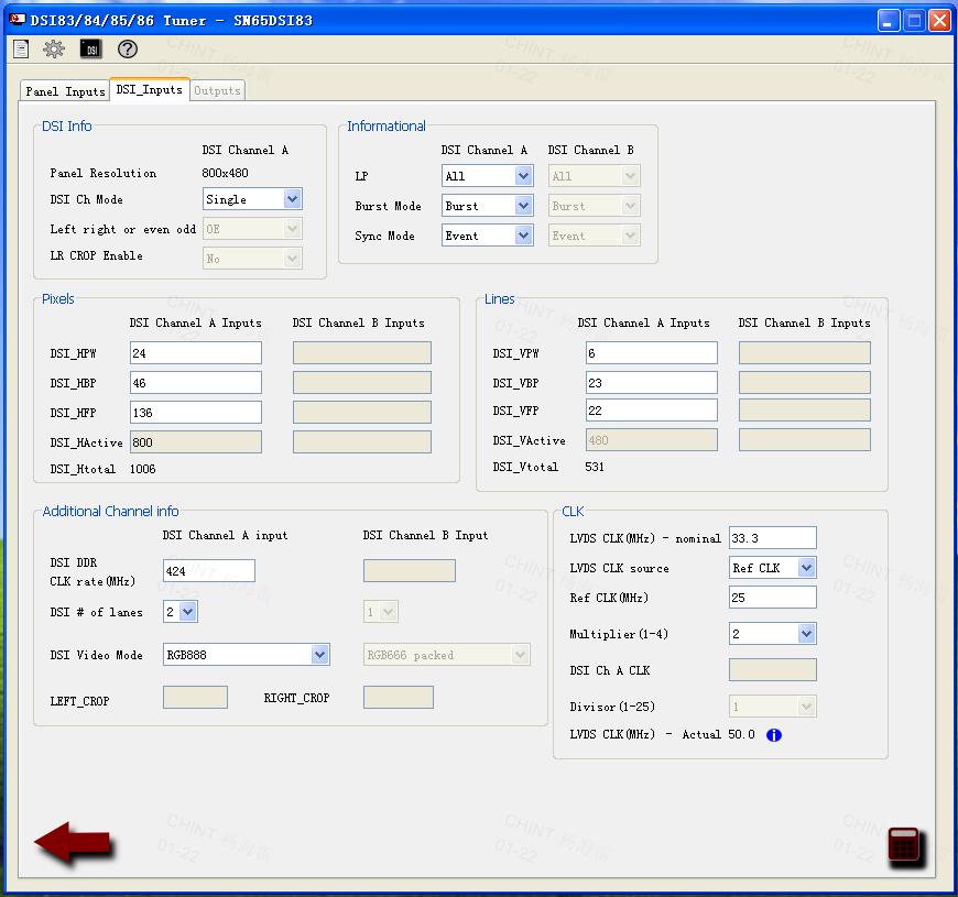
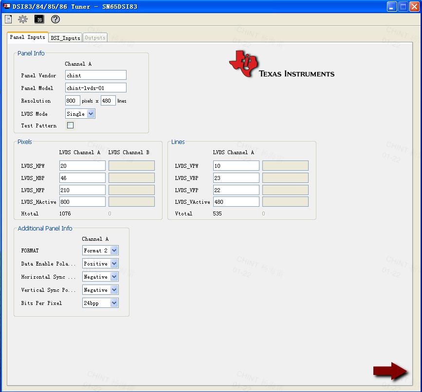
2. I have attached the new 25M initialization sequence. Is there an obvious problem with this?
