


Part Number: TUSB1002A
Hi TIer
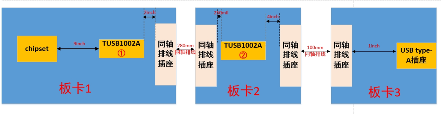
I recived the issue about 2 TUSB1002A system check. I have provided some initial guidance to the customer and would like the product line to verify these points and provide further technical details.
Please review the following proposed responses and provide confirmation or corrections:
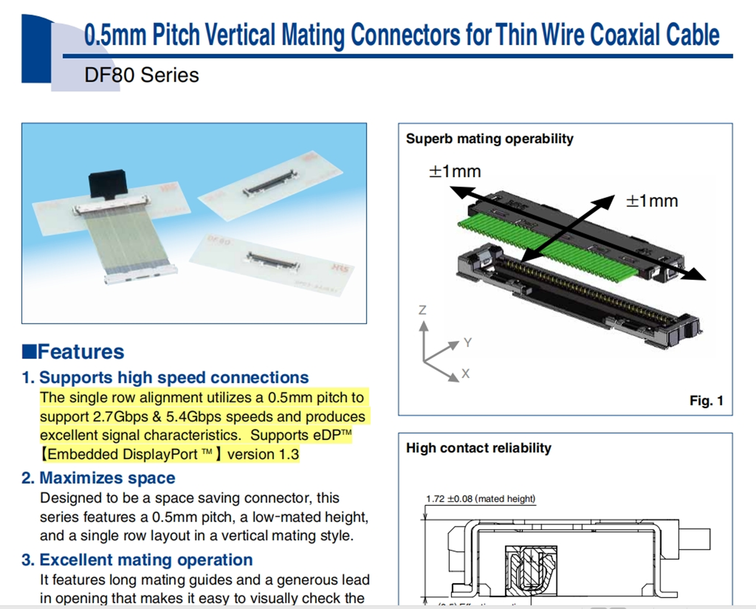
- According to the Hirose DF80 series datasheet, the connector is rated for up to 5.4Gbps. The customer is concerned whether 10Gbps USB 3.2 Gen2 signals can physically pass through this interconnect. Specifically, will the link automatically negotiate down to 5Gbps (Gen1) due to the connector's bandwidth limitation, or will it cause significant signal integrity failure :
- Proposed Response: During the USB link training (LTSSM), the system initiates handshake sequences (Polling and Rx.Detect) to determine the highest mutually supported data rate. If the physical layer (interconnect/cable) introduces excessive signal integrity issues—such as high Bit Error Rate (BER) from a 5.4Gbps-rated connector handling 10Gbps—the link will likely fail the Gen 2 handshake and downshift to 5Gbps (Gen 1).
- Request for Expert: Can you confirm if the PCH/TUSB1002A combination typically handles this downshift in high-loss environments?
- Redriver Placement (Board 2 vs. Board 3):
- Proposed Response: The
TUSB1002Ashould ideally be placed on Board 2, as close as possible to the coaxial cable entry point from Board 1. Placing it on Board 3 after additional board-to-board loss may exceed the device's 16dB compensation capability, resulting in an unrecoverable signal.
- Request for Expert: Does TI have a recommended maximum pre-channel loss threshold before the signal becomes un-recoverable for the TUSB1002A in this stacked configuration? Which board is perfer to place TUSB1002A?
- Proposed Response: The
- EQ Configuration Recommendations:
- Proposed Response: Initial EQ settings should be based on the total insertion loss of the pre-channel (Board 1 + Connector + Coax Cable). Per SLLA406 (TUSB1002A Configuration Guidelines), we recommend choosing an EQ setting that closely matches the calculated dB loss at 5 GHz.
- Request for Expert: Given a 32AWG coaxial cable (likely ~2-3dB/meter at 5GHz) plus two connectors, could you suggest a specific starting EQ setting from Table 1 of the datasheet?
Best regards,
Tony Liu

