This thread has been locked.

If you have a related question, please click the "Ask a related question" button in the top right corner. The newly created question will be automatically linked to this question.

SN75LVDS83B: SN75LVDS83B: CLKIN frequency

Part Number: SN75LVDS83B
Other Parts Discussed in Thread: SN74HC14,

San Giorgio di Piano, 04 March 2026

Hi,

   we developed and produced a process control board with an HMI interface more than one year ago.

The board has an 800x600 pixel TFT display both with RGB and LVDS interface. The latter is obtained with the Texas Instruments transmitter SN75LVDS83BDGG. 
During the initial tests, you helped us solve some problems with your E2E Design Support forum (see https://e2e.ti.com/support/interface-group/interface/f/interface-forum/1423192/sn75lvds83b-clkout-problem). With your suggestions and a squarer (SN74HC14) on the CLKIN signal, we were able to control the 800 x 600 pixel LVDS display.

Now we would like to drive a larger and higher resolution display with 1024 x 768 pixels.
Thus, the CLKIN signal frequency was changed from 40 MHz to 65 MHz.
After two weeks of testing and verification, we are unable to get it to work. Unfortunately, with these frequencies and our equipment, we have great difficulty examining the signals involved, so we decided to ask for your support.

Can you help us? Any suggestions are welcome.

Thanks in advance and best regards.
Gianluca Angelini
Software department

  • Hi Gianluca,

    Thank you for linking the previous thread for my context. Can you go into more detail about what is not working?

    • What testing and verification was done?
    • What type of equipment was used for this testing and verification?
    • Are you able to lower the PCLK below 65MHz and see a difference?

    Best,

    Jack

  • Hi Jack,

      It's great to hear from you again after such a long time. Below I'll answer your valid questions.

    The equipment used for testing and verification consists of:

    1. Two 10.4-inch displays from different manufacturers, with a resolution of 1024x768 pixels and an LVDS interface.
      Both displays work perfectly when connected to a VGA, HDMI -> LVDS bridge card.
    2. A complete application development microcontroller board with a graphics display controller that has a TTL RGB 888 interface.
    3. Our interface board for the microcontroller board that takes care of various aspects (power supply, field connections, serial drivers, buffered digital I/O, conditioned analog I/O, etc.). Among these aspects there is the conversion from TTL RGB 888 graphics signals to LVDS with the SN75LVDS83BDGG component.

    The tests and verifications we performed are:

    1. Used the microcontroller board to drive TTL RGB displays with 800x600 and 1024x600 resolutions: they works.
    2. Connected an LVDS display with 800x600 resolution: it works.
    3. Configured the microcontroller board for displays with 1024x768 resolution.
    4. Connected LVDS displays with 1024x768 resolution: they don't work.
    5. Changed the pixel refresh rate (PCLK), horizontal and vertical front and back porches to try to see rectangles on the 1024x768 display, but after dozens of attempts, we were unsuccessful.
    6. Changed the pixel clock edge between rising and falling.
    7. Changed the graphics signal driving capability of microcontroller between low, medium, and high.
    8. Searched for a TTL RGB display with 1024x768 resolution of but couldn't find one.
    9. We examined both TTL and LVDS graphic signals with an oscilloscope.
      Unfortunately, the oscilloscope we have has a 60 MHz bandwidth, and it's really difficult to see the signals clearly and accurately (it probably wouldn't be easy even with a better instrument). Almost all of them have a very low excursion and non-repetitive behavior, making them difficult to trigger and correlate.

    As described in point 5 above, we tried different pixel clock frequencies (PCLK) without seeing any benefits on the 1024x768 display. Honestly, the variation (which occurs on the oscilloscope) has little effect on the display. As described in point 2, I recall that an 800x600 display works well with the corresponding 40 MHz PCLK signal.

    I hope the information provided above is clear and complete; I look forward to hearing from you.
    Thanks in advance and best regards.
    Gianluca Angelini
    Software department

  • Hi Gianluca,

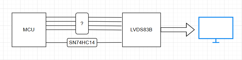
    Below is what I have captured for a high level block diagram. Can you let me know the MCU part # and what other ICs are in-between the MCU and the SN75LVDS83B?

    Was there a reason for placing additional ICs in-between the MCU and the LVDS83B? What is the distance between the MCU and the LVDS83B?

    Thank you for the additional context on the testing and validation done so far. Below are my additional comments

    • For evaluating 65MHz digital signals, the rule of thumb is that you need 3x the scope BW at the minimum. If we need more accurate measurements then a 200MHz scope is required. But let's see how far we can go without going into detailed measurements
    • What are the video timing requirements for the 1024x768 display? Is there a datasheet?
    • For the MCU, how fast can it drive signals from the I/O pins?

    Best,

    Jack

  • Hi Jack,

       sorry for the delay, but I had some urgent, non-interruptible work over the last week.

    Your high level block diagram is correct. The used MCU part number is R7KA8D2KFLCAC from Renesas and there are no other components between MCU and SN75LVDS83B.

    The reason we interposed the SN74HC14 squarer on the clock signal was to improve its edges. In fact, even though our oscylloscope wasn't adequate, the PCLK signal seemed too rounded. Adding this single IC allowed to run the LVDS display with 800x600 pixels.
    On our interface board there is a 3 pins jumper that connects pin 31 of the SN75LVDS83B (CLKIN) either directly to the PCLK signal from MCU or to the same squared signal from the SN74HC14. In the numerous tests described in the previous reply, we tried with the jumper in both positions. In fact, the HC14 gate propagation time (about 20 ns at 3.3 Vdc power supply) has a significant impact at these operating frequencies.

    The distance between MCU and SN75LVDS83B is about 100 mm. Unfortunately, they are so far because there is also a passage between different boards with connectors and positions to respect.

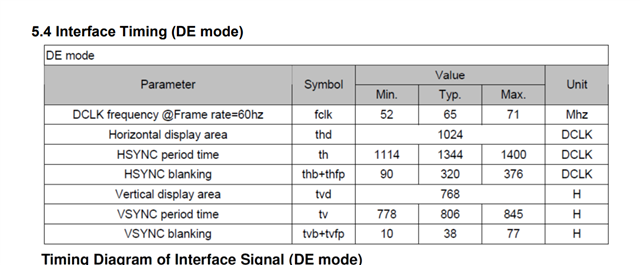
    The video time requirements of LVDS 1024x768 display can be found on pages 13÷15 of the attached data sheet.

    The MCU pins that control the display are part of a complex internal section called GLCDC = Graphic LCD Controller that has many possibilities and configurations. I honestly can't answer the maximum frequency of its signals, but the GLCDC section should drive a WXGA display (1280 x 800 pixels) and reach a maximum resolution of 2044 lines × 2040 pixels.

    Please ask if I have not been clear and complete.
    Thanks in advance and best regards.
    Gianluca Angelini
    Software department
  • Sorry, I forgot the display data sheet.

    Regards
    Gianluca

    AM-1024768Y8TZQW-TA1H.pdf

  • Hi Gianluca,

    My responses this week might be delayed as I'm working on many items in parallel. From the MCU datasheet I found the following electrical specifications on the GLCDC.

    Max timing looks to be 54MHz for parallel RGB888 (see Note 1) with VCC >= 2.7v. 

    Display datasheet has a minimum DCLK frequency of 52MHz. Have you tried operating at 52MHz?

    The reason we interposed the SN74HC14 squarer on the clock signal was to improve its edges. In fact, even though our oscylloscope wasn't adequate, the PCLK signal seemed too rounded. Adding this single IC allowed to run the LVDS display with 800x600 pixels.

    This approach is concerning because this does not sound quantitatively based. It is expected to have the edges of higher speed signals round out. Data is sampled on either rising or falling PCLK edge. If the oscilloscope used did not have enough bandwidth, it is difficult to say that improving the edges was the root cause.

    The SN74HC14 will add propagation delay which impacts setup and hold time. What voltages are the SN74HC14 and the MCU being operated at?

    Best,

    Jack