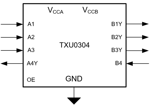
TXU0304: TXU0304 Recommended input level when disconnecting supply

Part Number: TXU0304
Other Parts Discussed in Thread: TXB0304

I raised this question a while ago and heard only that TI was investigating. The thread is now locked and there was no reply...

"In the datasheet for the TXU0304 specific mention is made of isolation between power domains when turning the part partially off.

"9.3.5 VCC Isolation and VCC Disconnect
The outputs for this device are disabled and enter a high-impedance state when either supply is <100 mV or left floating (disconnected), with the complementary supply within recommended operating conditions. It is recommended that the inputs are kept low before floating (disconnecting) either supply.

"What is the effect of an input being high when the domain to which it is associated is turned off? Does it make a difference if the high GPIO falls with the supply voltage rail?"

...and I had a follow-up comment...

"Additionally, does it make  difference to the recommended operating conditions if the OE pin is taken low but an input is still high when the associated power domain switches off?"


Our testing indicates there is no effect, but we may not be covering all cases and there may be internal states that we cannot anticipate.

Nevertheless, we are trying to bring all inputs low. Does it have to be all inputs, no matter which side of the buffer, or only the inputs on the side that is having power removed?

  • Hi Alex,

    We have received your inquiry and will respond shortly.

    Regards,

    Jack

  • Thank you Jack.

    I am specifically interested in the case where only one supply is shut down. 

    If it helps, we have two supplies: 1.8V and 3.3V. It is the 1.8V that turns on and off. You can assume the 3.3V side is permanent.

  • Hello Alex,

    I could not see any issues when one supply was left floating while an input was driven. Testing involved switching floating supply and OE reference voltage.

    I only saw current draw from the supply when VCCA was on, input was driven and VCCB was left floating. Additionally, OE state didn't make an impact on the current draw.

    Regards,

    Josh

  • Thank you Josh. This is at least a little encouraging.

    In our case, OE drops low and then VCCA (1.8V) is switched off while VCCB is left high (3.3V) at all times.

    The input on the VCCB side is driven high while VCCA is off and OE is low (UART Tx over which we have no control).

    Inputs on the VCCA side may be high before or after OE drops and - if high - droop with the VCCA supply as it turns off.

    Two outputs on the VCCB side have 10k pull-ups to keep the lines high when OE is dropped.

    Our testing shows no unexpected function of the buffer (hi-z inputs and outputs as described in the datasheet), and - more importantly - no additional current draw in that state.

    When you say that you "only saw current draw from the supply when VCCA was on, input was driven and VCCB was left floating" what current draw do you mean? More than 1uA into VCCA and more than 2uA Ioff?

  • Hi Alex,

    We are still looking into this and will provide update soon.

    Regards,

    Jack

  • Hello Jack,

    Any update on this?

    I'm particularly interested on whether current might change if the input on the always-powered side (VCCB for us) is driven high while the OE pin falls and the VCCA side is then unpowered.

    I imagine VCCA and VCCB are interchangeable with this part as it appears to be otherwise symmetrical from a power perspective (particularly with the other parts in the range featuring different I/O ratios).

    Also clarification of the statement "only saw current draw from the supply when VCCA was on, input was driven and VCCB was left floating". What was the nature of the current draw? Which input was driven?

  • Hi Alex,

    Thank you for your patience on this one. We will provide response tomorrow.

    Regards,

    Jack

  • Hello Alex,

    I set up the TXU0304 similar to what you described. My data is found below. 

    • For outputs B1Y and B2Y, I added an external pull-up resistor (4.7kohms) to VCCB
    • B3Y is left floating
    • B4 is tied to VCCB

    Test 1 (OE tied to VCCA)

    When both VCCA and VCCB are turned on, ICCA = 0.512uA while ICCB = 1.4mA.

    When VCCA is turned off, ICCB = 0.63uA

    Test 2 (OE tied to VCCB)

    When both VCCA and VCCB are turned on, ICCA = 0.22uA while ICCB = 1.4mA.

    When VCCA is turned off, ICCB = 1.15uA

    In my previous response where I said "only saw current draw from the supply when VCCA was on, input was driven and VCCB was left floating" Only A1 input was driven to VCCA and ICCA was ~0.6uA

    Regards,

    Josh

  • Thank you Josh. This is almost right, but...

    Your testing with OE shorted to VCCA is very close to our setup but differs in timing.

    Our case is where OE is 1.8V and goes low, VCCA is 1.8V and turns off after OE goes low, and VCCB is 3.3V always.

    • Short A1, A2, and A3 to VCCA, pull-up A4Y with 100k to VCCA (to simulate GPIO of a processor)
    • Short B4 to VCCB, pull-up B1Y and B2Y with 4k7 to VCCB, leave B3Y floating
    • OE switched to VCCA with a 10k pull-down

    I am specifically asking about a sequence alluded to in the datasheet.

    1. Start with the pins in the conditions above and VCCA at 1.8V, OE at 1.8V, and VCCB at 3.3V
    2. Switch OE so the 10k pulls it down to ground (or just short OE to ground)
    3. Then turn off VCCA (it's not disconnected but drained with the power supply, so you may ensure it drains with a parallel resistor from VCCA to GND - maybe 10k).

    The datasheet 'recommends' that the inputs should be low before turning off VCCA but doesn't say why. We don't do this and our testing indicates it doesn't matter. The 'recommendation' says nothing about the state of OE.

    • We drop OE low before turning off VCCA
    • Input B4 is on the VCCB side that doesn't turn off; does it matter if we leave it high?
    • Inputs A1, A2, and A3 stay high and, after OE goes low, drop with VCCA; can this cause an uncontrolled condition?
      • Could it be that the recommendation is to not drive the inputs on the VCCA side high while VCCA is unpowered?

    We want to know...

    • ...why there is a recommendation to set the inputs low before turning off one of the supplies?
    • ...whether it matters if the inputs on the always-powered side (VCCB) don't go low?
    • ...whether it matters if the inputs on the side that turns off (VCCA) stay high but follow the power to that side as it turns off?

    We were stung by an uncontrolled condition with the TXB0304 where one supply is turned off but not the other (against the datasheet 'recommendation') and we want to be sure there's no uncontrolled or undocumented state for the TXU0304 in like conditions.

  • Your testing indicates that, with OE low, VCCA off, and VCCB on then the only draw should be ~0.6uA-0.7uA into VCCB.

    This is acceptable to us, but not higher.

  • Alex,

    We have received your updates, however Josh is out of office and will get back to you as soon as he is back. 

    Regards,

    Jack

  • Hello Alex,

    See my response below:

    1) Why there is a recommendation to set the inputs low before turning off one of the supplies?

    I'm not 100% about this recommendation. From my testing, I didn't see any difference when the input was driven High, Low or Floating

    2) Whether it matters if the inputs on the always-powered side (VCCB) don't go low?

    No, it does not matter

    3) Whether it matters if the inputs on the side that turns off (VCCA) stay high but follow the power to that side as it turns off?

    No, it does not matter

    Regards,

    Josh

  • Thank you Josh.

    While I am uncomfortable that the datasheet includes an apparently spurious recommendation, I am satisfied that your testing and mine shows no issue.