DS160PT801: Review the schematic

Part Number: DS160PT801

Hi Sir,

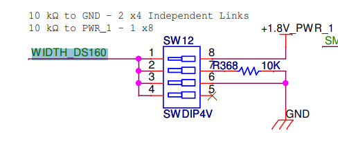
Could you please help review the schematics and provide your advice or comments?
Thank you very much for your support.

Schematics: ds160pt801 with FIBER.pdf 

  • Hi Henry, 

    I will review by the end of the week.

    Best,

    Charles

  • Hi,
    Please see my response: 

    1. 

    For all straps, use recommend resistors to pull up and pull down. Do not directly tie strap pin to power or GND. 

    2. PCIe lanes: 

    •  AC coupled once: OK
    • downstream (FPGA->GF) on B channels, upstream (GF -> FPGA) on A channel: OK

    3. Please ensure supply rails can support maximum current draw listed in page 12 of the data sheet.

    Best,

    Charles

  • Hi Sir,

    Could you please also review the layout file and provide your comments?

    Thank you very much for your support.

    ds160pt801 with FIBER layout file:ds160pt801 with FIBER_0508a.zip

  • Hi Henry,

    I have a response by Thursday.

    best,

    Charles

  • Hi Henry,

    Please see my comments:
    - We recommend ground void under AC coupling capacitors to a dept of ~2 layers. This helps compensate for impedance change caused by capacitor pads.
    - Ensure all high speed traces are impedance matched to 85 ohms. Are the High speed traces on layer Int5 layer impedance controlled? I don't see the reference plane above and below. 

    - Ensure Vias are back-drilled.

    - We recommend a Via anti-pad that follows the 10/20/40 drill/pad/anti-pad rule. 

    - Please match all P and N diff pairs within 5mils. This is not the case currently. For example: D9_retimer_PER0+ = 2364 mils, D9_retimer_PER0- = 2334 mils

    Verify that the solder mask and solder paste patterns follow the examples on pages 55-56 of the DS160PT801 datasheet

    Please reference our High Speed PCB layout appnote for more detailed guidance. https://www.ti.com/lit/an/snla426/snla426.pdf

    Best,

    Charles