This thread has been locked.

If you have a related question, please click the "Ask a related question" button in the top right corner. The newly created question will be automatically linked to this question.

DP83825I: DP83825I: DP83825IRMQR : Device only working in 10Mbps - part 2

Part Number: DP83825I
Other Parts Discussed in Thread: DP83825EVM

Hi Team, 

this is a follow up thread to the issue already created addressing the data requested from the support end  -  DP83825I: DP83825IRMQR : Device only working in 10Mbps

Please find the replies to the queries in the same :

  • Are you performing any stress testing on the boards? (EFT, ESD, ...)
    • No, we have not done any stress test in the device
  • Were these 2 units failing originally or did they start failing after a certain point?
    • They were working fine initially , but issue started all of a sudden in a boot with no particular changes done
  • What is the link partner in these tests?
    • The link partners tested with the device are as listed along with multiple laptops from DELL , HP (with different POE injectors like POE160S )and ethernet switches from TP-link ( LS110P and LS108P) and other similar brands
  • What cable length is used?
    • Tested using cables lengths  - 1m , 3m , 5m , 10m 
  • Do you notice any other symptoms from the failing ICs?
    • The wired connected was displayed in laptop , but on further inspection the link was turned on to 10 Mbps mode only and hence the camera ( the device in which the PHY is being used ) could not stream video
  • Can you provide a register dump of a failing IC vs a working one in the link up condition? 
    • Please find the attached register dumps.


  • please find the changes in the register with the working and non- working devices .

  • Hi Amal,

    From the register dump I can see the non-working PHY does not link up and is not detecting the link partners advertised modes. If this problem is following the PHY and the PHY worked originally but now fails, its possible the PHY was damaged. One way to confirm this is to place the PHY on the known-good DP83825EVM and see if the EVM works correctly. If so, I believe something in the design has damaged the PHY.

    Do more of your boards begin to exhibit this behavior after enough power cycles, or is the scope limited to these 2 devices? 

    Are you able to show the entire MDI path in the schematic? I can take a look to see if some other issue is present in implementation.

    Best,

    Shane

  • Hi ,

    We have only two non working boards and yes , the device showed these issues after a lot of power cycles . No hardware reworks were done on the boards.

    We have replaced the fault IC in working setup, but still the issue is prevailing .

    PFA MDI path for the reference 

  • Hi Amal,

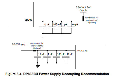
    The decoupling scheme for VDDIO and AVDD can be improved to follow the datasheet recommendation, though I wouldn't expect this in-itself to prevent link up. 

    The magnetics you're using are slightly out of our recommended spec for insertion loss, and I do not see a turns ratio tolerance metric. We evaluate our PHYs with a turns ratio tolerance of 2%, so I'd recommend using magnetics meeting this if possible.

    The only other discrepancies I see here are the ethernet connector (does not appear to be an RJ-45) and the addition of PoE circuitry. To confirm, when you place the failing device on a DP83825EVM, the EVM no longer works? If so, this suggests the device has been damaged. Certainly let me know.

    Best,

    Shane

  • Hi Shane , 

    as part of the debugging we also tried increasing the capacitance in the VDDIO and AVDD rails , but the issue still persisted.

    We have tried to integrate the magnetics part with LP41660ANL , but the issues still persisted.

    As per you recommendation , we tried replacing the IC in the EVM kit , the results were the same : PHY not linking up properly.

    We have already assembled over  70 number of devices and tested and qualified in EMI/EMC testing ( RE , RS , EFT, CE, CS, ESD ) and also conducted thermal ,accelerated ageing and other product reliability ( including endurance and IP testing ) test cases . But we could not reproduce the issue in any of the cases.

    Please guide us in the same. 

    Can we consider this as a case of faulty samples?

    In that case , what are the precautions that we must adhere to once we are planning for mass production. Please advise.

  • Hi Amal,

    If these failing PHYs are not working on the EVM as well then yes it appears the PHYs are faulty or were damaged in the manufacturing process. There are two paths forward I can think of for investigating further:

    The first step I would recommend is to narrow down where the PHYs began failing. Was the board failing as soon as it was manufactured? Was it after the board was in use for some time, was it after ESD/EFT testing,... This would give us an idea of whether the part arrived in a nonworking state or was damaged in use.

    If any testing/manufacturing issues are ruled out, you can submit nonworking units to TI's customer return process with the help of your local assigned TI engineer if your company has one. Otherwise, here is the link to begin this process: https://www.ti.com/quality-reliability/faqs/customer-returns.html?keyMatch=customer%20return&tisearch=universal_search.

    Best,

    Shane