TUSB7320: USB 2.0 HS Detection Handshake Issue

Part Number: TUSB7320
Other Parts Discussed in Thread: TUSB7340, TUSB7340-EVM

Hello,

I am testing a design which uses the TUSB7320IRKM, and it is behaving unexpectedly.

When a USB 2.0 device is connected, the enumeration process fails. Windows 11 device manager indicates that a USB device is connected, but is not functioning correctly (device descriptor request failed).

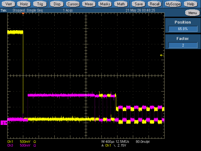
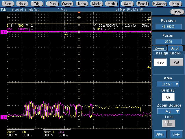
The USB high-speed detection handshake process appears to begin normally (see fist attached image), but the K-J chirping does not cease before the 10ms reset period is exceeded, and the process restarts after ~100ms (see second attached image).

I believe this to be caused by a hardware configuration problem, however, I have been unable to identify the cause of the issue.

What is the recommendation for next troubleshooting steps?


Additional details:

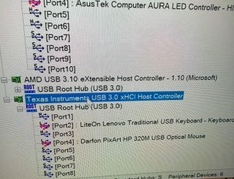
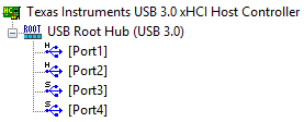
This TUSB7320 implementation is question is based on the TUSB73x0 datasheet (Rev Q) and TUSB7340EVM reference implementation (with preference to the datasheet for differing parameters), but without an attached EEPROM and with only the USB 2.0 signals connected. All USB 3.0 pairs are not connected in this design. The TUSB7320 initializes successfully as a PCIe endpoint, and is recognized under Windows 11 with the SLLC448 version 01.00.00.0A driver.

Attached figures:

Handshake_Closeup.jpg

Handshake_MultiCycle.jpg

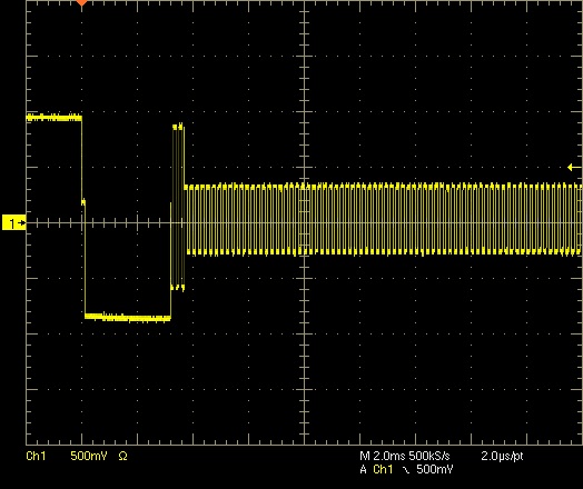
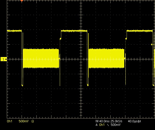
Note: Oscilloscope measurements are taken using a differential probe.

  • Hi,

    Are you able to capture a protocol trace of the USB communication using a protocol analyzer?

    Can you test on multiple USB 2.0 devices and reproduce the same issue?

    Can you probe both the D+ and D- separately, so both waveforms are shown?

    The HS enumeration process should follow these steps:

    1) HS host detects a FS connection

    2) HS device initiates HS handshake

    3) HS host responds with multiple JK chirps

    4) device detects these chirps and enables HS terminations

    5) HS communication begins

    I'd like to see this handshake as shown in the following slides:
    https://www.ti.com/content/dam/videos/external-videos/ko-kr/9/3816841626001/6305893689112.mp4/subassets/what-is-usb-2-0-high-speed-detection-handshake-presentation-quiz.pdf

  • Thank you for your guidance, Vishesh,
    I do not have a USB protocol analyzer, but one is now on order.


    I have repeated the testing with multiple USB 2.0 HS devices, however, all device communication failed in the same manner. I also tested a USB 1.1 LS device and the OS still failed to determine the device descriptor, which is concerning.
    I have reworked the measurement setup with two active probes similar to the presentation you linked. The first attached image should be analogous to page 4 of the presentation, and shows steps 1-4 being executed.

    First attached image

    The chirp K-J sequence still continues for ~100ms, however I discovered that the timeout/restart process shown in my first post only applies for the first few handshake attempts, after which the host does stop the chirp sequence after 104ms and begins sending microframes. As can be seen in the second and third attached images, there is data being transferred in the microframes, but I cannot decode it with my current measurement setup.

    Second attached image

    Third attached image

    Since the LS device also failed, and there are microframes (eventually) being successfully being sent, the communication problem may not be in the HS handshake process.

  • HI,

    I have repeated the testing with multiple USB 2.0 HS devices, however, all device communication failed in the same manner. I also tested a USB 1.1 LS device and the OS still failed to determine the device descriptor, which is concerning.
    I have reworked the measurement setup with two active probes similar to the presentation you linked. The first attached image should be analogous to page 4 of the presentation, and shows steps 1-4 being executed.

    Yes, it seems that both the host and device enable the high speed terminations, but afterwards we see no progress. I'm not sure its takes 104ms to begin SoF packets transfer. 

    Are you able to share a schematic of your TUSB7320 implementation. What OS driver are you using for this project?

    Seeing that a LS device fails we may need to wait for  the protocol analyzer to see exactly what's happening here.

  • The 104ms figure is the measurement from the start of the handshake (DP pulled up → SE0). The time between the terminations being enabled and the first microframe is 101.6ms. This timing seems to be relatively consistent so far.

    Due to client confidentiality, I cannot share the schematic publicly, but I can send it to you privately if there is a mechanism to do so.

    The OS is Windows 11 (build 26100.8246), and the driver is version 01.00.00.0A of the “TUSB73x0 xHCI Filter Driver for Win8/8.1/10” (SLLC448).

  • Hi,

    Can you test the default host controller driver from windows?

    I have requested friendship over E2E, you can send the schematics over through a private message.

  • I have sent you the schematic via a private message.


    I retested using the default Windows-11-provided host controller driver, however the results are unchanged.
    This is an image of how the TUSB7320 and downstream device present in Windows device manager:

    Attached Image

    I will test using another host computer running Windows 10 (the latest officially supported OS on the SLLC448 driver description) over the next couple of days as well.

  • Hello, 

    We are OOO today for the U.S holiday. Expect a response by EOD tomorrow.

    Thanks,

    Ryan

  • Hi Jordan:

       Can you send Schematic for review? USB3 device works fine?

    Best

    Brian

  • Hello Brian,

    I have sent the confidential schematic to you via private message. 

    This implementation is USB 2.0 only; the USB 3.0 pairs are left NC. 

    Thanks

  • Hi Jordan,

    I shared the schematic with Brian internally. He will take over supporting this issue.

  • Hi Jordan:

       Host PCIE_ TX should be connected to PCIe M2 PERX, I'm surprised you still can see USB2 enumeration data even with wrong connection.

       Did you see the TI host under device manager or USBtreeviewer?

       Can you measure signal amplitude for high speed signal? it looks more like host disconnected due to some reason.

    Best

    brian

  • Hi Brian,
    The signal direction annotations on the schematics is from an internal annotation scheme. I apologize for the confusion. The actual electrical connections are made in accordance to the M.2 Specification – this is illustrated in Annex Figure 6-2 (attached).

    M.2 Spec Signal Directions (Fig. Annex 6-2)

    Attached is an image from Windows device manager, as well as a PCIe root complex scan, that shows the TI device connected to the PCIe root complex. There does not seem to be any evidence (event logs, warnings, etc) that suggests a PCIe disconnection during operation.

    Windows Device Manager Image

    PCIe Root Complex Scan (Annotated)

    Regarding signals levels, I do not have the equipment to probe the PCIe signals, but the USB HS microframes have an amplitude of ~430mV on each data line – though with ~30% overshoot on 0-1-0 transitions.

    I will check the USB status using USB Tree Viewer and reply to this post with the results.

  • From device manager, it seems TUSB7340 host controller was detected by system.

    Are you able to zoom out overshort area and measure signal amplitude?

    Best

    Brian

  • I have remade the test setup to reduce probe length, now the post-bus-reset microframe overshoot appears to be lower at about 12-15% - so the 30% was likely a probing artifact. Attached is a figure of this measurement, taken ~105ms after starting the handshake.

    Amplitude Test

    I have also run USBTreeViewer and I have attached both the TUSB7320 host entry and an entry for an attached device.

    Additionally, I was able to connect the USB protocol analyzer and probe the signal. I have attached the .pcapng file from connecting a USB 2.0 flash drive. This file should be openable using Wireshark. Strangely, the device is not picking up the microframes after the 3rd bus reset, but it does show the handshake → KJ-pairs for 100ms → bus reset behavior as observed on the oscilloscope. I have attached these files as a zip archive.

    TUSB_Analysis_Results1.zip

  • Let me review the trace, some reason caused the reset after KJ and can not complete USB2 enuration.

    Best

    Brian

  • Please let me know if there is anything not in the .zip file (sent in the prior response) that I can provide.

    Thanks

  • There is not much information in the trace.

    Can you remove R47/R48 and try again? what is the device connected to this port?

    Regards

    Brian

  • R47 & R48 Were already removed in all prior tests mentioned in this message chain in order to disconnect the onboard device, which is an onboard USB-capable microcontroller, as per this diagram:

    Connection Diagram with Annotations

    When the onboard microcontroller was connected to the TUSB7320 via R47 & R48, it displayed the same communication failure as the other tested USB devices (device descriptor request failed). When a different USB host was spliced in (R47 & R48 removed) to the microcontroller via a cheap USB hub, the microcontroller enumerated and functioned correctly.

  • Sorry, I mean just replaced  R47/R48 by 0 ohm resistor and test again.

    Do you have TI TUSB7340EVM to try?

    Regards

    Brian

  • I have replaced R47 and R48 with 0-Ohm jumpers and retested. Unfortunately, there was no change in outcome (device descriptor request failed, verified via USBTreeViewer).

    Test Result

    Regarding an evaluation kit, I do not have a TUSB7340EVM (seems to be marked as obsolete?).

    I can find and purchase a unit if it will help with the debugging process, however, please note that when the device is configured as per the below figure (independently from the TUSB7320), the microcontroller’s USB enumeration/operation functions correctly.

    Test Diagram

  • Hi Jordan:

        We do have TUSB7340-EVM to order at ti.com. I believe it will help to debug if v it's TI host issue ( I don't think so).

      So the microcontroller does not need Vbus to work?

    Best

    Brian

  • The microcontroller does not need VBUS – it is internally powered and does not need to use VBUS for USB detection. The microcontroller’s USB implementation has been verified with multiple other host controller ICs (using the configuration from my last reply), and it is functioning on other designs.

    The only new/unverified portion of the design is the TUSB7320 section.

  • Hi Jordan:;

      Can you remove R47/R48 and connect host DP/DM to an USB 2 connector to check if USB2 flash drive works ( need Vbus on USB connector?

    Regards

    Brian

  • Hi Brian,

    I have just tested a PNY USB 2.0 flash drive, and the results are the same (device descriptor request failed).

    To clarify the test configuration in the prior posts:
    In posts 3-5, the USB signals were pulled from the TUSB (via the unpopulated pads of R47/48) into a type-A socket with an external 5V VBUS power supply. The probes were attached at the socket side.

    When the USB protocol analyzer was used, the TUSB’s USB signal was connected to its input, and its output was connected was connected to a USB 2.0 flash drive.

  • how far is from PCIe slot to host  and host to microcontroller on PCB?

    Do you have Lecroy analyzer?

    best

    Brian

  • There is only 2cm in signal distance between the M.2 slot and the TUSB7320 on the device PCB, but the PCIe signals run approximately 22cm from the root complex (on CPU) to the device PCB. This M.2 slot has been validated with two PCIe gen 3 and gen 4 devices. I can shorten this to 15cm if absolutely necessary.

    The USB signal distance between the TUSB7320 and microcontroller is approximately 1.7cm. When using the external socket or analyzer instead of the microcontroller, the USB signal distance is about 10cm.

    Unfortunately, I do not have an analyzer from Lecroy, nor do I have the capability to directly probe the PCIe signals.

  • in Windows, can you download USBtreeviewer tool to check if TI host controller is there? There should be 4 downstream port.

    Regards

    Brian

  • USBTreeViewer shows that the TI host controller is present and has 4 downstream ports. Attached is a screenshot of USBTreeViewer with no USB devices attached to the TUSB7320.

    USB Tree View of TUSB7320

    Additionally, I have attached the detailed text report of both the TUSB7320 host with no devices attached, and a text report for a flash drive device (with the prior observed issue) in a .zip file.

    USBTreeView_TUSB7320.zip

  • HI Jordan,

    Thanks for the info, we're still working on root causing the issue.

  • Hi  Jordan:

        Are there PCIe slot on your system? I like to try TUSB7340EVM on your system. Maybe there is issue between TUSB7340 and microocntroller.

    Regards

    Brian

  • Unfortunately, the test PC does not have a PCIe slot available. However, I was able to find a commercial product with the TUSB7340 that I can add to the PC thorough a couple of adapters. I have ordered these parts.

    I do not suspect there is a physical link issue between the TUSB7320 and microcontroller due to the results of the prior tests. To avoid confusion, here is a diagram of some tested configurations:

    Tested Configs

    For additional hardware context, the USB signals are tapped off at the pads of R47 and R48. Therefore, the traces between these resistors and the microcontroller must work. The trace distance between these resistors and the TUSB7320 is very small (~3.5mm), and they are not shorted to each other or ground.

  • Hi  Jordan:

        Is your product a adaptor board on M2?

     1:  Does external USB host controller on the same system or different system?

     2:  can you send layout for review?

    3:  can  you try TI driver which at TI.com?

    Regards

    Brian

  • Yes, the product uses an M.2 form factor.
    1) I have tried external host controllers on both the host system and an independent system (laptop) in the prior figure.
    2) I have private messaged you with the product’s Altium PCB file. I can also generate Gerbers/ODB++ if needed.
    3) I have tried both the Windows default driver and the current TI driver (SLLC448) version 01.00.00.0A in earlier tests in this thread. I have just retested it, and the different driver versions did not seem to have an effect.

  • 1:

    1) I have tried external host controllers on both the host system and an independent system (laptop) in the prior figure.

    how do you try on the same  system which does no has PCIe slot?

    2: are there AC caps on PCH side on SSRX?

    3:We don't use Altium so it's not easy to review the layout.

    4: Did you use V3P3 supply form M2 connector, what is max current for V3P3?

    5: Can you ship one board to us so we can use Lecroy analyzer to help debug.

    Best

    Brian

  • 1) In the case of the same system, the mainboard has a host controller in the PCH and has a couple of extra built in host controllers. "External" in this context just means not the TUSB7320.
    2) While it is difficult to verify if there are TX AC caps on the mainboard due to density, the platform is manufactured by a reputable company, so it is unlikely they would violate the PCIe spec by omitting them.
    4) Yes, the 3.3V rail for the TUSB is from the M.2 connector (with heavy filtering). The M-Key socket should be spec compliant, and the mainboard QVL contains 10W devices (3A).
    5) I need higher approval to ship out a sample unit for testing. What country/province is your lab in?

  • We are at Dallas TX.

    Best

    Brian

  • Thank you for the clarification, Brian,

    I am private messaging you for shipping details.

    Additionally, I received a product with a TUSB7340 onboard. I have rigged it to the microcontroller on the device prototype as per the below figure:

    New External Setup

    This configuration works correctly and can be viewed on the USB tree view (port 2):

  • Was TUSB7340 onboard on the same  system with internal TUBS7320?

    Best

    Brian

  • Yes, they are both on the same system.

    The external TUSB7340 is connected to the same PCIe root complex as the internal TUBS7320.

    Device Manager with Both TUSBs

  • ok, let me check schematic again.

    Best

    Brian

  • Hi  Jordan:

      I didn't  see major issue for schematic, just few questions:

    1: I can't find this device, is this LDO or DC convertor? what current limit for this device?

    SV6324BE 

    2: PERST circuit looks pretty complicated, did you probe it to see anything abnormal?

    3: Can you probe 3.3v and 1.1v supply  to see if stable?

    4: did you try more boards?

    Best

    Brian

  • Hi Brian,

    1) “SV624BE” is an internal SKU for the On-Semi NCP6324 – A 2A synchronous buck converter.

    2) While PERST# does have additional circuitry, the TUSB7320 is connected ‘upstream’ of it, and is directly tied to the M.2 connector’s PERST# pin. I have probed the signal at the TUSB7320 during startup and did not observe any glitches - though I am not finished observing it under all conditions.

    3) I am working on probing the supply rails (3.3V, 3.3VA, & 1.1V). It is difficult due to the high density, and I will make another post with the results, but preliminary measurements suggest ≲70mVp-p of noise for each. 

    4) So far, the tests conducted in this thread have been spread across 4 boards, all of which display the same issue.

    Thanks,

  • NCP6324  is Buck device which has switching frequency at 3Mhz, but TUSB7320 PLL is low pass filter with 5-10Mhz bandwidth. that means this 3Mhz supply  noise can pass though into the device and causing lots of jitter. LDO is recommend for mixed signal devices like USB and PCIe.

    Can you try with external power source with 1.1v and 3.3v, GRST should be de-asserted after 1.1v and 3.3v are stable.

    Best

    Brian

  • I do not have an equipment setup that can inject 1.1V and de-assert GRST# while meeting PCIe’s ~120ms startup timing requirements.

    I am ordering in an LDO which I can rig in place of the NCP6324. I will post a reply with the results of the swap.

    Thanks for this insight

  • sure, wait for your update.

    Best

    Brian

  • I have replaced the 1.1V switching regulator with an LDO that has the same features (PG, SS, EN) and configured it to supply the correct voltage with the required soft-start period (>1ms).

    Unfortunately, the issue still persists unchanged.

    I am now working on probing the 1.1V, 3.3V, and 3.3VA rails (and GRST) to see if there are any abnormalities.

  • Thanks for update, waiting for your  supply waveform.

    Best

    Brian