MAX3243E: Startup Error with FORCEON/OFF

Part Number: MAX3243E

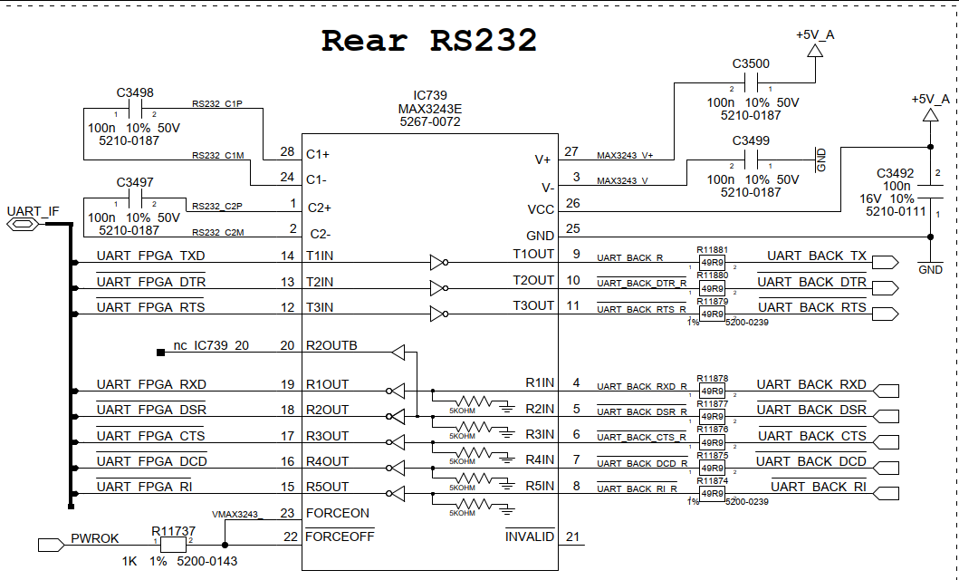
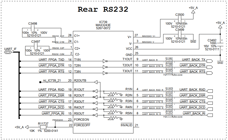
Hello, we have connected the FORCEON and FORCEOFF pin together through 10k to the same power supply voltage +5V. With that connection everything is working fine. 

During start-up of the CPU board the customer saw some signs on the COM interface.

So we connected the FORCEON and FORCEOFF pin together to the board reset signal. This signal is also 5V. The reset signal will be released > 50ms after the 5V are stable.

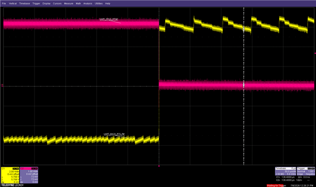
Now sometimes there is no communication via the MAX3243E. We see that the RTS signal is going to high state and after some seconds it will be low. But the FORCEON and FORCEOFF signal is every time high !

Is it not allowed to drive the FORCE signals after powering up the device?

Thanks and best regards
Working.png


Not_working.png

  • Hi Daniel,

    Today is a holiday. Please help give until next week for some feedback, thanks. 

    Best Regards,

    Michael. 

  • The bus pins have three states, high, low, and disabled (in the disabled state, the 5 kΩ resistor in the receiver will pull the line to GND).

    When the RTS signal switches between high and low states, then the only explanation is that the input signal also changes. Note that the TxIN pins must never float. Please check an oscilloscope trace of the T3IN and T3OUT pins. (Is the UART_FPGA_RTS line ever disabled? Do you have a pull-up/-down resistor on that line?)

  • Hi Daniel,

    What specific package are you using? I would double check your pinout matches either Table 6-1 or Table 6-2 depending on the package. Please provide a waveform of the T3IN and T3OUT as Clemens' mentioned. 

    It is just fine to control Forceon/off as you are doing. This is a common implementation that we recommend. 

    Also note that your capacitors are valued incorrectly. Please reference Table 10-1 for the proper values. Currently your charge pump caps are setup for 3.3V.

    Best,

    Ethan

  • Hi Ethan,

    we are using the SSOP package, so the pinout should match. I know about the charge pump caps, thx, but this is not the root cause. We changed already to 1uF. So if using Forceon/off during operation is possible, it looks like the failure is inside the FPGA. Or is it possible that the device is switching into a "stand-by" mode and is therefore not working anymore in some cases?

    No PU on the output signals of the FPGA. The failure also occurs if we have only RX TX connected between 2 identical boards. All other RS232 lines are not connected.

    Best, Daniel

    red = T3IN

    yellow = T3OUT

    charge pump caps 100nF in this case

  • Hi Daniel,

    I am not sure I fully understand your issue. But having Forceon/off being tied high is the correct move. When they are both this way, it disables the auto-power down feature. So it will not be a in a "Standby" or low power state. 

    That waveform shows that the T3IN and T3OUT are working properly. Please capture the T3IN, T3OUT pins while your issue is occuring.

    Best,

    Ethan