AM2634: AM2634 VPP Questions

Part Number: AM2634

Hello,

I have a few application-related questions concerning the state of VPP for the AM2634 for eFuse programming.

We've inherited the following design, where the VPP input is 1.6V:

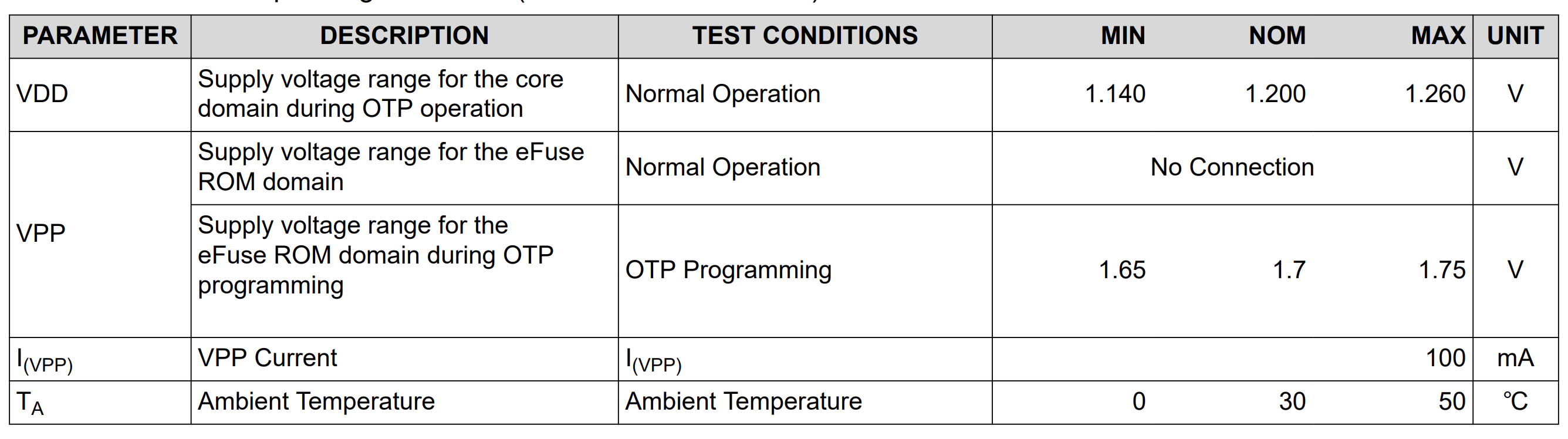
  • From the datasheet, I see that the VPP input is 1.65-1.75V. I presume this would make the 1.6V. source unusable correct (or is the operating voltage not as tight in practice)?image.png 
    • A couple of follow-up questions to the above requirements for the VPP input:
      • If we get a proper 1.7V input, should we also have a current limiting resistor in series to prevent the 100mA max, or is there already internal protection? I didn't see any current limiting resistor in the control-card schematic.
      • If we have a slightly high voltage level like 1.8V, would it be ok to just source from that w/ a voltage divider (since it seems like the required power draw is low) or is this not recommended?
  • For the "normal" mode, from everything I have read in the datasheet leaving it floating is the correct response. Given this, I'm curious about the following:
    • Would the pin being connected w/o either jumper be floating (since there is a cap to GND), or should it truly be floating and fully disconnected from anything in the "normal" state? I presume that is fine w/ the CAP to GND since the control-card has a similar setup.
    • Would there potentially be damage in the case of attaching the GND jumper? It's pretty clear that this definitely shouldn't be an option for "normal" operation (especially based on this forum post where it was heavily discouraged to connect it directly to GND: https://e2e.ti.com/support/microcontrollers/arm-based-microcontrollers-group/arm-based-microcontrollers/f/arm-based-microcontrollers-forum/1192877/am2634-1-7v-vpp-generation), but I am curious if there is potential that things actually may have been damaged. We noticed that power draw increases significantly when we tie it to GND when we initially were doing this, but have not observed any actual difficiencies in performance (currently, we do not rely on any eFuse programming, but it would be good to know if any boards where we have made this connection are potentially compomised).
  • Hi George,
    Thanks for the detailed write-up. Here are answers to each of your questions:

    1. Is a 1.6V VPP source usable?

    No — your presumption is correct. Per the datasheet, VPP during OTP/eFuse programming must be 1.65V–1.75V (1.7V nominal). 1.6V falls below the minimum spec, and we do not provide any margin data suggesting 1.6V is acceptable in practice. The window is intentionally tight because eFuse programming is a one-shot, irreversible operation — insufficient VPP risks a partial/failed programming pulse.

    2. Current-limiting resistor — is it needed, or is there internal protection?

    The datasheet specifies I(VPP) max = 100mA as an operating condition, but nothing in the documentation states that the AM2634 has internal current-limiting circuitry on the VPP pin itself. On the official AM263x-CC control card, VPP is generated by a dedicated LDO (TPS7A2117PDRV, per the actual CC schematic — 3.3V→1.7V) with no series resistor — the LDO's own regulation is what's relied on, not a discrete resistor. If you're building a custom supply path, size it so your regulator/source can supply up to 100mA pulses cleanly without a series resistor being required; our reference design doesn't use one.

    3. Sourcing VPP from 1.8V via a resistive divider

    Not recommended. Our documentation only describes two sanctioned methods for generating VPP:
    • An external LDO stepping a board supply down to 1.7V (this is what the CC does), or
    • The on-chip Analog LDO (ANALDO) — available on AM263Px/AM261x — temporarily reprogrammed to output 1.7V during programming and reverted afterward.
    A resistive divider is never mentioned as a valid VPP source. Given that eFuse programming draws current pulses up to 100mA, a divider's output would sag significantly under that load and is very unlikely to hold the tight 1.65–1.75V window reliably — risking a bad/partial fuse write. Use a proper LDO instead.

    4. Floating VPP with a cap to GND in "normal" mode

    This is correct and matches our own recommendation. The datasheet's decoupling table specifies a 0.1µF cap on VPP as standard. With the jumper open (nothing actively driving the pin) and just the decoupling cap present, this satisfies the "No Connection"/floating requirement for normal operation — it's the expected configuration, not a workaround, and matches the control-card's own layout.

    5. GND jumper — any risk of prior damage to boards where this was done?

    This is the part with the least documented certainty, but there's a relevant data point I found in a related E2E thread (AM2634: 1.7V VPP Generation) where we explicitly and repeatedly instructed a customer NOT to short the VPP test point (TP42) to ground, even during OTP Keywriter setup where U66 (the VPP LDO) wasn't populated. Our guidance there was firm: use an external 1.7V bench supply between TP42 and DGND — never a direct short to ground.
    That said, no documentation found (datasheet or forum) explicitly states whether tying VPP to GND during normal operation causes permanent/latent damage to the eFuse ROM domain. The datasheet's programming note only states "No voltage should be applied on the VPP terminal during power up and normal operation" — it doesn't describe the failure mode of a hard GND tie specifically.
    The increased current draw you observed when grounding VPP is a real symptom worth flagging — it's consistent with the strong discouragement in the forum thread you linked, but I don't have data confirming or ruling out permanent effects on boards where this was done. Since you haven't relied on eFuse programming on those boards yet and haven't seen functional deficiencies, there's no evidence of a problem today — but given:
    • The datasheet's explicit warning that eFuse errors "will render the TI device inoperable," and
    • TI's stated lack of liability for eFused devices,
    I'd recommend not fusing any board where the GND jumper was previously installed.

    References:
    • AM263x Datasheet — VPP Specifications & Decoupling Capacitor Requirements table
    • AM26x Hardware Design Guidelines — eFuse Power section
    • E2E: AM2634 1.7V VPP Generation (TI guidance against shorting VPP to GND)
    • E2E: AM263P4 Keywriter Related Issues (confirms VPP must remain stable/within spec during programming — instability isn't correctable by Keywriter error-correction features)
    Best Regards,
    Zackary Fleenor