TIOS102: TIOS102 - current limit in application

Part Number: TIOS102
Other Parts Discussed in Thread: TIOS101, TIOL112

Hello TI,

I'm designing with the TIOS102 and found an inconsistency in the datasheet (www.ti.com/.../tios102.pdf) regarding the current limit setting.
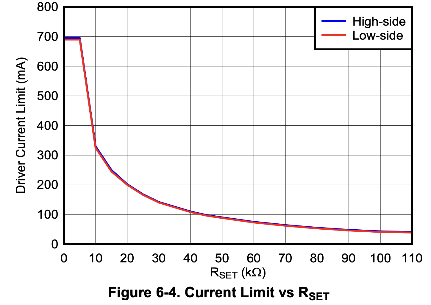
image.png


In the Typical Application section, the design requirements table says: Output current 200 mA → "Choose 250 mA limit with RSET = 27k"

However, Figure 6-4 (Current Limit vs RSET) and Figure 6-5 (TIOS102 vs TIOS101) show approximately:
- 15 k → ~250 mA
- 20 k → ~200 mA
- 27 k → ~155 mA

So according to the curves, 27 k would set the limit below the 200 mA output current from the example. 

Could you please clarify:
What is the intended rule for selecting RSET? Specifically, is the 27 k in the application example a datasheet error (and should it be ~15 k for a 250 mA limit, or 20 k for 200 mA)? Or does the current limit have a large tolerance (tens of percent), so that 27 k is meant to guarantee a limit above the 200 mA output current across devices and temperature?

Thank you.
Milan

  • Hello Milan,

    Thanks for the question and I understand the confusion.  This is not an error, but it could be documented better in the datasheet. Yes there is a tolerance range with regards to the current limit set by the RSET value.

    Please also review the Application Information Disclaimer in the datasheet that states the information in the Applications sections are not part of the component specification.  These sections are provided for guidance and information purposes only.  The information in the Applications sections of the datasheet do not provide any guarantees.

    The Figure 6-4 is a "Typical Characteristics" curve which are collected at a single temperature (25C) unless specified otherwise.  These figures may or may not include additional variables such as voltage or manufacturing process tolerance that could impact the curves.  This particular figure shows a single line that corresponds to a resistance, but this is really the minimum current limit curve for that resistance and the actual current limit may be slightly different from device to device.  

    The datasheet specifies a range using the 10k resistance as a test condition, but a min/max range exists for all resistance values which could be represented as multiple min/max curves in this figure.

    The TIOS102 is essentially a variant of the TIOL112 which supports IO-Link communication.  These devices share the same core driver and current limit circuits and I see that the figure in the TIOL112 datasheet does contain these min/max curves. So for now I'll refer you to this curve since it is also representative of the TIOS102 device.  

    Notice that the blue (Min) curve in the TIOL112 figure corresponds to the curves in the TIOS102 figure.  This means that the TIOS102 current limit will be 200mA with RSET = 20k, and ~155mA with RSET = 27k.  But some devices could be higher.

    The Applications section is based on the typical curve which shows that the device will be able to output~200mA before hitting the current limit with RSET = ~25k.

    As a note, the purpose of the figures in the TIOS102 and TIOL112 are slightly different. 

    The TIOS102 datasheet figure is showing that there is not a difference between the current limit when measured in a high-side or low-side configuration because the two curves are exactly the same. 

    The TIOL112 datasheet figure is showing the min/max range of the current limit but only at the ambient temp of TA=25C.

    Regards,

    Jonathan

  • Hi Jonathan,

    Thank you for the detailed explanation - reading the TIOS102 curve as the minimum limit and using the TIOL112 min/max figure as a reference makes sense.

    Milan

  • Hi Milan,

    You're welcome, I'm glad I could help.

    Regards,

    Jonathan