This thread has been locked.

If you have a related question, please click the "Ask a related question" button in the top right corner. The newly created question will be automatically linked to this question.

TCA4311A - Failed in the stop condition in the slave side

Other Parts Discussed in Thread: TCA4311A, TCA4311

Hello,

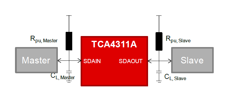
My customer have some questions about TCA4311A.

I attached their schematic and the waveform which failed in the stop condition in the slave side.

3108.TCA4311A.pdf

[Q1]

Why did it fail in the stop condition in the slave side ?

Please tell me what they should do to operate it normally.

[Q2]

It worked normally when they changed R203 & R204 to 4.7kOhm.

Why does it seems to be ?

Can you explain the reason ?

Best Regards,

Hiroshi Katsunaga

  • Hiroshi-san,

    Can you confirm the TCA4311A is being used by reading the top-side marking on the device and tell me what you read? I just want to verify 100% that this is not the TCA4311 non-A version.

    Also, have you tested this on multiple PCBs? Does the same failure happen on multiple boards?

    Thanks for the information on the pull-up resistors. You said 4.7kOhm resolves the issue. What was the original pull-up resistor value? 10kOhm?

  • Brian-san,

    Thank you for your fast response.

    ・The top-side marking as follows.

      <top-side marking>

        2711

        6KS

    ・They have tested this on multiple PCBs.

     The same failure happens on 2 boards. 

     (It is not all boards.)

    ・The original pull-up resistor value was 10kOhm.

    Best Regards

    Hiroshi Katsunaga

  • Hiroshi-san,

    I found a design document describing the best conditions for pull-up resistor sizing:

    "Choose Rpu, Master and Rpu, Slave such that the following conditions are satisfied


    6 V/us ≤ (0.4 * VCC) / (0.85 * Rpu, Master * CL, Master * 1e6 us/s) ≤ 8 V/us
    6 V/us ≤ (0.4 * VCC) / (0.85 * Rpu, Slave * CL, Slave * 1e6 us/s) ≤ 8 V/us

    Note: Choice of Rpu, Master and Rpu, Slave shall ensure I2C standard requirement of IOL ≤ 3 mA. See below example calculation.


    Rpu > (VCC – VOL) / IOL
    Rpu > (3.3 V – 0.4 V) / 0.003 A
    Rpu > 966 Ω"

    You will have to estimate the load capacitance, but if you follow this calculation, it may explain why the 4.7kOhm resistors are working and the 10kOhm resistors are not working. And it may depend on resistor tolerances, explaining why 2 boards fail while others pass.

  • Hi Brian-san,

    Thank you for your fast response.

    I told your additional information to my customer.

    They calculate it now.

    I will update the result later.

    They have some question about it.

    [Q1]

    Does this failure happen when their calculation result is out of range that you showed?

    Can you show the mechanism ?

    [Request1]

    Would you show this information to the datasheet ?

    [Q2]

    They have a additional information.

    It worked normally when they kept Rpu resistor( = 10kOhm) and delayed a timing of the stop bit.

    Are there the specifications in a timing of the stop bit ?

    Best Regards,

    Hiroshi Katsunaga