A related question is a question created from another question. When the related question is created, it will be automatically linked to the original question.
If you have a related question, please click the "Ask a related question" button in the top right corner. The newly created question will be automatically linked to this question.
I have DP83640 PHY on board connected to MAC via RMII. LED link is lit and ACT is blinking, but pinging gateway doesn't work. Any idea what may be wrong?
Thanks for your email, I've sent you schematic files and register settings.
Getting a bit more into details we are trying to make DP83640 working with SFP modules. You have two versions of schematic, one is for copper ethernet (proper copper with transformer, RJ45 and so on), second one is for SFP module. Also you have two sets of register settings, one is for copper and one for SFP. Board with SFP modules is working fine, but it doesn't work with copper ethernet. Can you advise what's wrong, please?
Thank you for all the information. I have been looking through your register dump you provided and I found something interesting for Reg 0x01 and Reg 0x10 for your copper configuration.
Reg 0x01 is reading that link is not established, but Reg 0x10 is.... could you do a few successive reads on both these registers and send them to me?
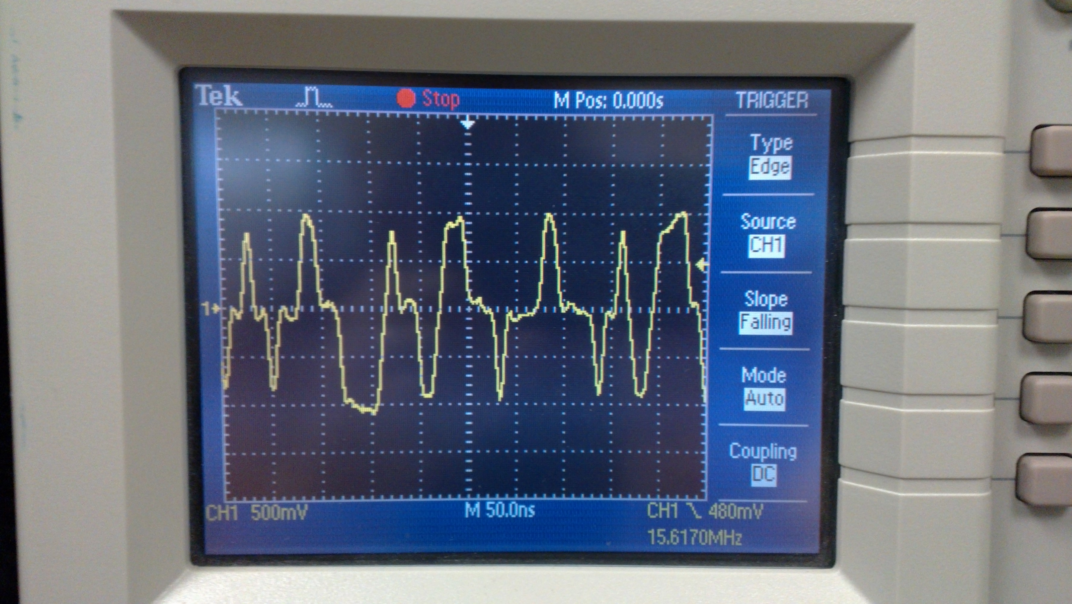
When cable is connected I can see LINK LED lit and ACT LED blinking. Maybe it will attract your attention that I'm getting big number of errors while pinging:
I see that the both your copper and fiber devices are linked and have completed auto-negotiation. I was looking over your schematics more and I have a few questions.
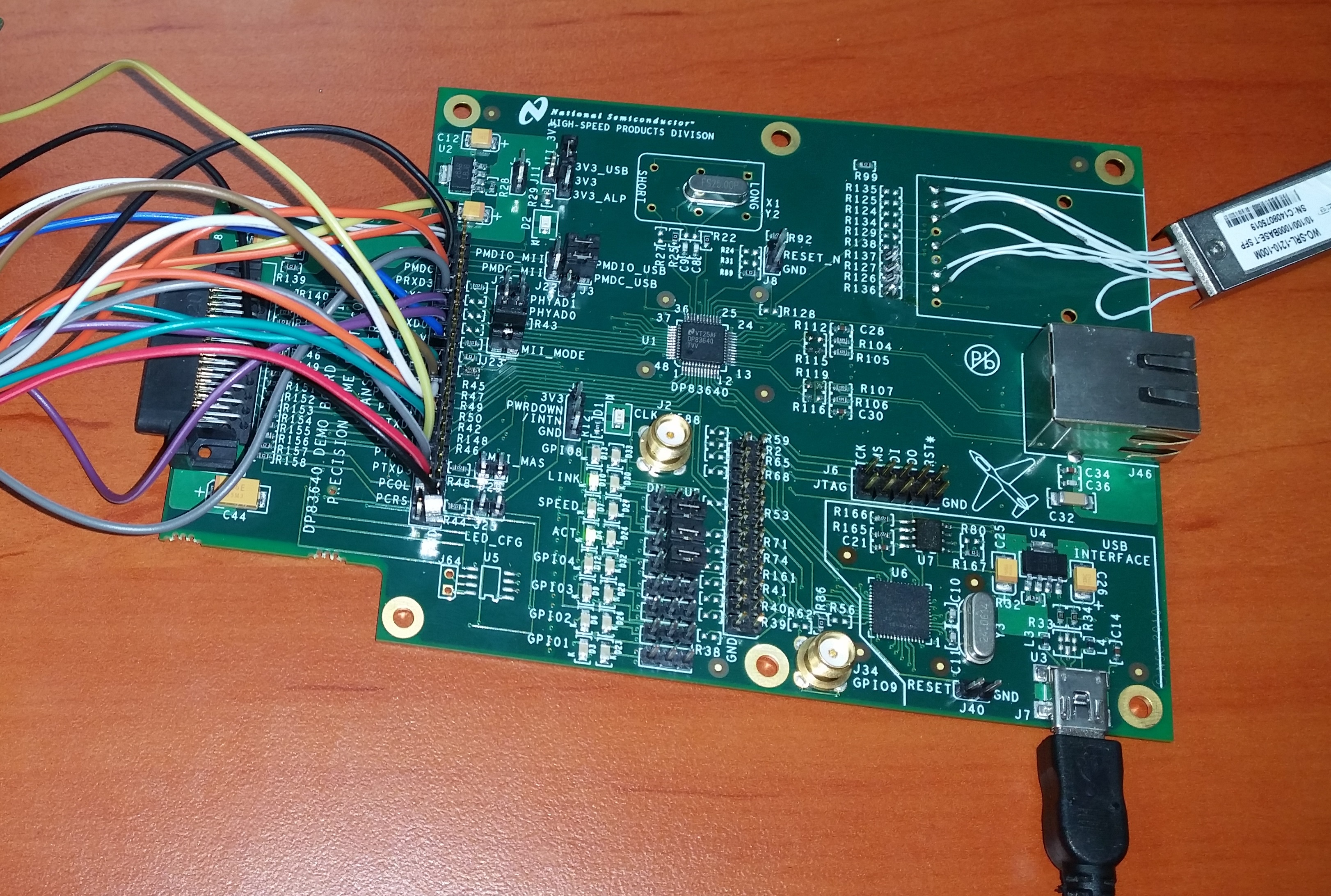
1. what is the overall block diagram of how you are testing this?
2. Why in each pdf are there 2 PHY ics? (i.e. you have 2 copper implemented phys on one pdf with slightly different configurations and one pdf with 2 fiber implementations)
3. what do the waveforms look like on the TD and RD pairs?
Hi Ross,
On PHY which is used for fiber autonegotioation is disabled by strapping it for fiber.
1.) I have Freescale i.MX287 processor with embedded switch connected to PHYs. Then we connect the board either directly to computer or via switch to LAN, and then try to ping from board to computer and from computer to the board.
2.) There are two boards, one is assembled with fibers (SFP) and the other one is with copper ethernet. The processor has embedded switch and we want two ethernet ports, that is why we have two PHYs in each pdf. Configuration of each PHY is same except they are strapped to diferent addresses, one is 0x01 and the other one is 0x02.
3.) Do you want TD and RD waveforms before transformer? Do you want them when I have a link or unplugged?
I've grabbed some waveform, however I think scope is not good enough for that sort of data. Do you have any idea what should be minimum bandwidth and sampling frequency to analyze ethernet data?
If we strap PHY to fiber mode and then connect SFP module using connections from Figure 9-2 from datasheet it works fine, but with copper it refuses to work.
It has eventually started working. I didn't find an exact reason, but after changing CPU and software it works so it seems not to be DP83640 related problem.
Hi Jacek
Have you solved your problem? I try to use AM335xx and SFP. I think, I used wrong PHY from Microchip and now I think about DP83640 but I don't have any experience with SFP and this PHY. Do you have some advices for me? Im wondering if i have to connect SFP to this PHY. Where are you from?
Regards
Pawel
I was unable to run DP83640 with copper ethernet, but I managed with SFP. You need to use schematic as for fiber, strap it for fiber and then it should work. I'm based in England.
Thank you for your answer. I'm designing in Altium with DP83640 EVB schematic for a FIBER. Could you take a look at my schematic with DP83640? Jacek is a polish name so I thought that you are in Poland - like me.
I bought DP83640T Evaluation Demo Board and I connect it to an Evaluation board with microcontroller. With copper every think is all right. But SFP doesn't work. I changed resistors on board for a fiber, I put RXER to the ground with 2.2 resistor. I have no idea what is going on. Do I need to change something in PHYs registers for a SPF?
We have been trying to do run the same DP83640 in fiber mode. We verified the board function via copper and when we switch to fiber, strapping the PHY for fiber mode (per datasheet specs), the communication isn't working. Did you strap yours in hardware or software? Any info is greatly appreciated.
Hi Wes,
I strapped mine in hardware. Remember that in fiber mode speed autonegotiation (10/100) will not work, so you need to turn it off on the other end and set to your fiber's speed.
I assumed that you have fiber at DP83640 end, then it goes through media converter and the other end is copper. So on copper end (i. e. computer) autonegotioation (10/100) has tu be turned off, that is it has to be set to either 10 or 100 according to what is fiber end set. This is because that two stations can't autonegotioate speed.