This thread has been locked.

If you have a related question, please click the "Ask a related question" button in the top right corner. The newly created question will be automatically linked to this question.

TUSB2046B

Other Parts Discussed in Thread: TUSB2046B, TUSB2077A

Hi,

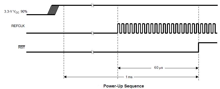
I have a problem which I am suspecting might be related to the reset pin of the device.  I.e. cause the RESET pin to not occure witin 100us to 1ms.

Our customer has a power supply with a rise time of 20ms (for whatever reason) for VBUS to go from 0V to 5V.

I have simulated this slow rise time by adding a 300mH inductor in series on the VBUS power line.  When I add the inductor the USB hub and devices are not picked up by windows.

When I remove the inductor the devices are picked up.

What can you suggest ?

Also is there maybe a power on reset IC from TI that you can suggest ?

  • Hello,

    According to USB 2.0 specification for all device and hub implementation the time to start communicating with the host must be less than 100ms.
    Texas Instruments recommends 100 μs to 1 ms of reset timing because this interval ensures that the connection is stable at the devices before any requests will be sent to them. Therefore a 20ms reset time should work ok.

    Please share the customer's schematics, I would like to verify if the hub is set up correctly.

    We usually suggest using an external RC circuit (15K pull-up resistor and .1uF cap) for the RESET terminal, actually, that is implemented in our 2046B EVM. However, I will look into an IC solution that can meet with the requirement.

    Regards,
    Joel

  • Hi,

    I have added the schematics for the part of our circuit surrounding the hub.  I am only using two of the ports.

    Would really appreciate if you can help find the problem.

    Also another question.  If I were to keep reset pin pulled low with a micro for example or MOSFET and then after all my circuits have started up (VBUS reached 5V) pull it high, will this work ?

    8738.Schematic Prints 03.pdf

    2553.Schematic Prints 04.pdf

    Schematic Prints 05.pdf

    Schematic Prints 06.pdf

    Schematic Prints 07.pdf

  • I have done some more tests. With the longer rise time of the VBUS supply (about 20ms from 0V to 5V) (also for 3V3 supply then ofcourse) the clock of the 6MHz crystyl on the TUSB2046B never starts.

    When I have a rise time for VBUS of 0V to 5V with about 500us everything seems to be happy.
  • Does it matter how long after 3.3VCC reaches 90% of its value the reset occurs ?

    I.e. can I keep reset pin low until lets say some time after 3.3V VCC reacheed 3.3V and then wait for clock to be active and then pull RESET high ?
  • I have now also tried using 15K resistor with 0.1mF capacitor for reset pin.  Does the same, works for short rise time of VBUS (around 4ms) but not for VBUS rise time around 20ms.  Pleaes can you look at previous posts and questions in this discussion.  I need some answers please.

  • Considering my two scenarios I have some data:

    Case 1:  about 4ms rise time for 3V3 VCC:

    Comparing 3V3 VCC (yellow) to clock (green):

    It looks like the clock is only running about 5ms after 3V3 VCC reached 90% (not correct, clock should run during last 60us before reset goes high)

    Comparing 3V3 VCC (yellow) to RST (green):

    Reset goes from low to high pretty much together with VCC although clock is not even running yet. 

    This case works though and my USB devices are picked up and run correctly.

    Case 2:  about 30ms rise time for 3V3 VCC:

    Comparing 3V3 VCC (yellow) to clock (green):

    clock is running already by the time 3V3 VCC reaches 90% (correct, clock should be running before reset goes high).

    comparing 3V3 VCC (yellow) to reset (green) 

    This case does not work.

    My conclusion: 1. Case 1: should not work but it does

                                2. Case 2: should work but it does not.

           3. Does not look like the correct timing can be achieved with one fixed resistor and one fixed capacitor over entire USB standard allowed range for rise times of 3V3 VCC ??

    Something else I did pick up is that if I zoom out on the clock it seems to run stop run stop and then run.  In spite of this still the 4ms rise time case works but not the 30ms rise time for 3V3 VCC.  Also from what I understand from our end user client is that it appears that the work / not work border is somewhere around 4ms (stop working when rise time is longer than somewhere around 4ms).

  • Is anyone from TI going to reply here ???, it has been 5 days now...

    I have made some progress.

    I removed the diodes D1 and D2 I have on my circuit diagrams as posted on previous posts.

    I am only using 2 of the downstream ports and for most of my PCB's it seems to work using a 10K resistor and 100nF capacitor for reset pin.

    For some PCB's though it does not work completely. For the 30ms rise time case it picks up the hub but does not pick up the tablet device connected to the one downstream port. It does however sometimes charge the tablet on the downstream port but not consistently. For these ones that does not work completely for the 30ms case it does seem to work fine for the about 4ms rise time case...
  • You need to hold the reset pin low (between 100 μs and 1 ms is recommended) after 3.3-V VCC reaches its 90% and then release it as shown below.


    The case 1 above seems to be correct, just make sure that the reset is being asserted for 100 us to 1 ms.

    Regards

  • Please can you elaborate more and comment on the previous posts.

    1.
    Does it matter how long after 3V3 VCC reached 90% of its value (0.9 x 3.3V = 2.96V) before the reset sequence must start ?
    2.
    Can you recommend constant values for R and C that will work ?
    I do not see why this is so hard. Can you suggest values for R and C that will work for all rise times of 3V3 VCC < 100ms ?
    3.
    I am using 10K and 100nF that seems to be working for most of my PCB's but not all. I found one so far that picks up the USB hub but
    not the tablet device connected to one of the downstream ports. For this not working PCB I have tried 1.5K, 4.7K, 15K, 22K and it works
    less or the same, i.e the hub is picked up but not the tablet on the downstream port or the hub is not picking up at all.
    4.
    Or am I mistaken, is it even possible to have one value for R and C that will work for any rise time < 100ms for 3V3 VCC ?
    5.
    Can you suggest a reset supervisor IC that can take care of this ?
    6.
    Your picture does not make sense to me as the voltage at the reset pin is closely following the 3V3 VCC (see pictures in previous posts).
    I do not have much control over this for various 3V3 VCC rise times.
    7.
    Have you look at the circuit diagrams, is there maybe something else wrong ?
    8.
    The clock signal seems to be one then off then on then off and then on and continue to be on. Is this the way TUSB2046 does it ?
  • There is only one requirement for the reset signal timing. The minimum reset pulse duration is 100 μs. At power
    up, this time is measured from the time the power ramps up to 90% of the nominal VCC.
    Please, try 15K pull-up resistor and 1 uF cap.
    I have reviewed your schematics and it seems to be set up correctly. I'm looking for an IC that meets the requirements.

    Regards
  • 15K with 1uF also does not work.

    1. I really don't understand why one R and C value recommended by you does not work for all.  Why does the forum recommendation have all different values for R and C's ?

    2. Also by pulse do you mean the reset line needs to be low for 100us to 1ms after 3V3 VCC reaches 90% (2.96V) ? 

    3. As you know for an RC circuit the capacitor charges slowly and it is not possible to get a quick 0V to 3V3 rise time as required from your graph. Also not for any rise time between 1ms and 100ms ??

    4. Also what about the clock, please see question in previous posts.  Why does the clock go on then off then on then off and then fully on ??

    5.  When I look at the case 1 you say is correct, by the time 3V3 VCC reaches 90% of its value the reset pin is pretty much at the same voltage as 3V3 VCC seaing that the RC circuit is following it.  How is this then a 0V for 100us to 1ms to VCC pulse ??

  • Actually, the  R and C values that I recommended were used in our TUSB2077A/36/46B  EVMs, and  have been implemented by several customers. Could you send a scope cature, showing Vcc, reset and XTAL at power-up

    By saying a pulse I mean that you need to hold it low at power up and then release it.

    The RC circuit have to hold the reset pin low for somewhere within the range. Note that the minimum High-level input voltage for this terminal is 2V. 

    Can you check the status of the SUSPEND output and OVRCURn/ input?

    Is the Tablet a high-power device?

    Could you provide some trace captures using a USB protocol analyzer between the host and the hub?

    Regards

  • Hi,

    I have reverted back to 15K resistor and 0.1uF capacitor.

    It works / does not work as follows:

    For VBUS rise time of around 4ms:
    - Generic USB hub is picked up by windows (TUSB2046B).
    - Downstream port 1 is picked up by windows. This is the "Tablet" port. My Samsung galaxy S3.
    - Downstream port 3 is picked up by windows. This is the FTDI232 chip.

    For VBUS rise time of around 30ms:
    - Generic USB hub is picked up by windows (TUSB2046B).
    - Downstream port 1 is NOT picked up by windows. This is the "Tablet" port. My Samsung galaxy S3.
    - Downstream port 3 is picked up by windows. This is the FTDI232 chip.

    I have posted results comparing RESET pin, VBUS rise and XTAL at startup in previous post. Will make some more for the 15K and 100nF case.
    I was playing with the recommended 15K and 100nF before and it seemed 10K was working better over a range of PCB's.

    SUSPEND is LOW for all cases working and not working. OVRCURn are high for all cases working and not working.

    I do not have a USB protocol analyser.