This thread has been locked.

If you have a related question, please click the "Ask a related question" button in the top right corner. The newly created question will be automatically linked to this question.

J1708 5V Supply Protection

Other Parts Discussed in Thread: SN65HVD1780, SN65HVD1780-Q1

Hi everyone,

We are looking to create a robust J1708 node that will be used in automobiles.  We had some questions regarding the loading configuration of a J1708 node, shown here:

1.)  Consider the +5V as the output of our buck converter. If the Serial Data Bus line going to A is at a higher voltage, say 6V or shorted to battery (12V), would we need to protect our 5V supply from reverse current?  Does this answer depend on whether driver/receiver are enabled/disabled?

2.)  Ultra-low power is a necessity for us.  We would like to put the chip in a standby mode with uA current draw, does this loading configuration allow that?

Thank you,

Tony

  • Hello Tony,

    1. Lets consider the two cases which can occur on the bus: dominant or recessive

    Recessive: For the J1708 standard, the recessive state occurs when the driver of the RS-485 transceiver is disabled. The A and B pins go into high impedance, and the bus voltages are biased to a positive differential logic level by R1 and R2. In this case, if the serial data bus is pulled to a higher voltage than +5V, there will be a potential drop from the serial data bus to the output of the buck converter (through 4.7k+47ohms). Since the bus pins are in a high impedance state, the path for current flow will be back into the buck converter (though there is some sizable resistance in the path). In this case you may need to supply the converter with some protection from reverse current. Since I don't know the characteristics of your buck converter I can't give a definite answer on that but the question that should be asked is: can my buck converter survive  around 1.47mA of reverse current?

    I got that number from:

    V = 12-5 = 7V

    R = 4.7k + 47 = 4747 ohms

    I = V/R = 1.47mA

    Of course this is calculated for a DC short since the caps will block the DC path to ground. For short transients, those caps will provide a low impedance path to shunt energy away from your buck converter.

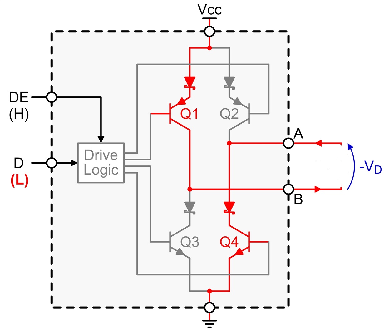
    Dominant: In the dominant state things will be a little more complicated. The driver will be enabled and will pull the bus lines to a negative differential state through a Full H Bridge like this:

    In this case, there should be a low impedance path from the A line to ground through the device, so as long as the RS-485 transceiver is rated for this condition, you should be ok. 

    Enabling and disabling the receiver will have no effect on this issue. 

    2. As for standby mode, there is no reason why this setup would prohibit you from using the feature. 

    To sum it all up, there is a possibility of reverse current at the buck converter output which may or may not be a problem based on that part. If the device is sensitive to reverse current, it might be a good idea to look into a protection scheme. 

    Also as a side note, I noticed that your scheme matches the node load circuit in this app note: 

    Except the capacitors are much larger in your schematic (2.2mF vs. 2.2nF). I'm not sure if that was intended or not. 

    Best Regards,

    Casey 

  • Hi Casey,

    Thank you for the very good explanation.  Let's consider a system with a 24V battery:

    1.  Recessive: According to the equation above, this would require my buck converter to sink 4mA of reverse current.  We plan on using the LMR16006Y but couldn't find anywhere a "Maximum reverse current" spec, is there another term we can look for?

    2.  Dominant: Consider the worst case where the 24V Battery is shorted to the A line. If we then try to drive this to ground through the transceiver (dominant state), the only thing limiting current is the 47 Ohm resistor, is that correct?  If so, we then have a steady state current of 511mA flowing through the resistor and the device. The SN65HVD1780 has a 200mA "Driver short-circuit output current", which is much less then the 511mA, will it survive?  This would also require the 47 Ohm resistor to be rated for 12.2W, whoa!  

    You are correct, those caps should be 2.2nF.

    Best wishes,

    Tony

  • Hello Tony,

    1. I wish I could help with this question, but unfortunately I'm not very familiar with the internal topology of the buck converter, so this might be a better question for the team responsible for that device. I don't know how the buck converter will respond to a higher-than-expected potential at it's output. 

    2. For the SN65HVD1780, the transceiver is guaranteed to survive a short to at least 70V on the A line while driving a dominant state. The short circuit output current is a parameter of the driver output, while the larger current you are referring to would be sourced from the 24V battery. Now, as for the actual current going through the resistor, you may actually see less since the diagram is simplified and there are other resistances in the path like the on-state resistance of the H-Bridge transistor and there will be a drop across the protection diode too. If you would like, I can set this up in the lab and measure the voltage drop across the 47 ohm resistor during this condition which will give you the current flow too. This would give a feeling for the power rating required for that resistor. 

    Best Regards,

    Casey 

  • Hi Casey / Tony,


    Here is the link to the forum that support the simple switcher: e2e.ti.com/.../858

  • Hi Casey,

    That experiment would be very informative and appreciated.

    Thanks,
    Tony
  • Hey Troy,

    I did some testing with this device today and here's what I can conclude:

    If I directly short a DC supply to the A pin while driving low, the device limits the current to around 110mA for voltages up to 15V. If I increase the voltage at the pin up to 16V and above, the current limit decreases to lower and lower values. This is to prevent the device from exceeding its maximum junction temp as the power dissipation increases. (As the voltage increases, the current limit decreases to balance out the power dissipation).

    This means that if you have a series resistor in the path between the device pin and the short, the largest current you will see through the resistor is about 110mA (I confirmed this by testing with a series power resistor). Since the resistor is 47 ohms, you will see about a 5V drop at maximum across the resistor, leading to a power dissipation of around .56W.

    For this reason, I would go ahead and use resistors rated to 1W or higher just to be safe.

    I hope this is helpful to you!

    Best Regards,
    Casey
  • Hi Casey,

    Great results!
    Just to be sure, the device under test was the SN65HVD1780, correct? Do you think the automotive version SN65HVD1780-Q1 would exhibit the same response?

    How high of a DC voltage did you test to?

    Thanks!
  • Hi Tony,

    Yes, I was using the SN65HVD1780 for these tests and the highest DC voltage I tested to was +70V. The highest voltage drops across the resistor are actually around 15V DC before the device starts to significantly limit current. At 70V, the drop across the resistor was only around 1.8V because the transceiver's current limit is lower.

    The SN65HVD1780-Q1 will behave the same way.

    Best Regards,
    Casey