This thread has been locked.

If you have a related question, please click the "Ask a related question" button in the top right corner. The newly created question will be automatically linked to this question.

TUSB211 - USB 2 Compliance Measurement Issues

Other Parts Discussed in Thread: TUSB211

Hello @ all,

we want to use your TUSB211 in our next project.

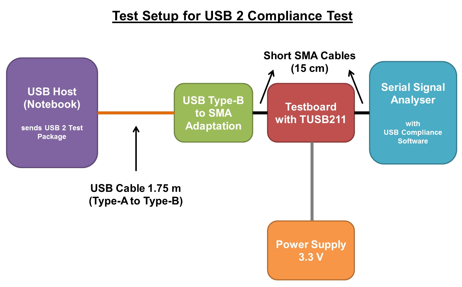
So i made a testboard for that IC with four SMA connectors for the Data lines (D+ and D-, input and output) and pin headers to change EQ-levels.

Then i connected this testboard with an approx. 2m USB cable and an USB host which sends USB 2 test packages. The other side of the testboard i connected to a serial signal analyser with USB 2 compliance software on it.
After i run the compliance test i passed with TUSB211 disabled and failed it with TUSB211 enabled.
I looked at the test package with the oscilloscope and i saw curious spikes for long "0" and long "1" sections (see attached pictures).

I think that is the cause for not passing the usb compliance test.

I tested also other testboards but it was always the same issue.

Can you help me with this?

Thank you in advance!

regards,
Mustafa

Measurements.pdf

  • Hello,

        The issue seems to be related to the signal frequency, the TUSB211 detects when there is a HS signal flowing thru DP & DP, therefore the pattern of long 1's and 0's might be confusing the detection circuitry. Is it possible to reduce the number of 1s and 0s until the issue is gone?


    Regards,

    Diego.

  • Hello Diego,


    thank you for your answer.

    The pattern we transmitted over the TUSB211 was the official USB 2 test pattern (test_packet) which you describe in the "Detailed Design Procedure" in the datasheet of the TUSB211. In this test pattern there are long high and long low sections integrated, so i can't reduce that numbers manually.

    For an host compliance test the test pattern was sent by a notebook and here the described issues occured.

    But if i made a device compliance test, where the pattern was sent by an USB Stick the issues were gone and the TUSB211 worked without any problems. The test pattern looked quite better as the host test pattern.

    So what do you think is the problem? Is the functionality of the TUSB211 really dependend on the form of the test packet?


    regards,

    Mustafa

  • Hello Mustafa,

    Not at all, as A first approach I thought that a longer pattern was transmitted. Could you send a scope capture of both patterns without re-driver to find a root cause.

    Regards,
    Diego.
  • Hello,

    I have exactly the same problem than Mustafa : I would like to run a Host USB2.0 electrical test but the "ENA_HS" pin goes down when I transmit Test_packet through the transceiver. I'm using TI's Tusb211 evaluation board and the Test_packet is transmitted by an application processor.

    No problem occurs when the Tusb211 is removed, and the only thing I can see is that the "ENA_HS" pin falls after 500us of inactivity on the DP-DM bus.

    Have you found any solution to fix this problem ?

    Regards,
    Nicolas
  • Please refer to section 8.2.2.1 of the TUSB211 datasheet for detailed test procedure for taking eye-diagrams.

    Regards,

    Undrea