Hello,
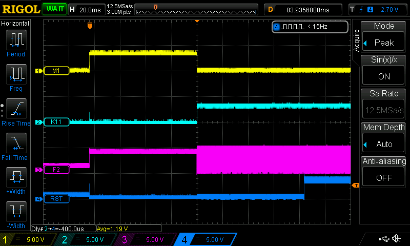
I am using the DP83879IVS in MII mode, coupled with a Beckhoff ET1100 MAC. I notice an intermittent glitch, which happens rarely during power-up - after several tens/hundreds of power cycles: The input pins 45, 46, 48 of DP83879 (TXD0_B, TXD2_B, TXD3_B) seem to act as if they are outputting some charge / current. These pins are connected in my circuit to the ET1100 MAC, and to 2.2K pull-up / pull-down resistors. These pins are sampled by the MAC after power-up, and sometimes (rarely) the sampled values are wrong. During the sample time, the supplies are well stabilized (several tens of milliseconds after power-up), the DP83849 is held in reset since initial power-up time, and the clock input of DP83849 is stationary, no clock, pulled up by a 2.2K resistor. Probing by oscilloscope doesn't show any voltage glitch on these pins, just system noise of around 50mV peak-peak around the pull-up/down voltage of 0V or 3.3V. However, when I remove these pins (by lifting them from PCB), or when the entire DP83849 is removed, there is no more problem, even after thousands of power cycles. As soon as the DP83849 is soldered (including these pins), the problem shows after some tens/hundreds od power cycles.
What would be very useful is to have an equivalent input schematic of the on-chip circuitry inside the DP83849IVS on these 3 pins - are they just connected to a pair of CMOS gates plus a pair of reverse-biased ESD diodes? Or is there something more? I suspect that these pins may be driven during the time when there is no clock, some tens of milliseconds after power-up.
The frequency of wrong power-ups seem to depend on the slew rate of the 3.3V supply (common supply for DP83849 and ET1100 MAC) - less frequent with ~100uS risetime, more frequent with ~500uS risetime. The sampling moment is at ~80mS after 3.3V rising.
A related question: what is the input current current of the pins which have on-chip pull-up/down? For example, TXD0_B has on-chip pull-down. Datasheet shows maximum +/-10 microAmps on all inputs - this is probably wrong for the pins with on-chip pull-up/down. Also datasheet recomends external 2.2Kohm pull-up/down resistors, to counter-act the on-chip pull-up/downs. Could you be more specific about the input current that is sourced/sinked by the on-chip pull-up/downs?
Another un-related remark: datasheet SNOSAX1F revised September 2015 contains several errors related to the numbering of the timing values. The number in the AC timing requirements table does not correspond to the number in the referred picture. See for example timing T2.32.1 at page 17, which probably should correspond to T2.27.1 at page 29. Or, anotehr example, look at page 23: there are two waveforms with timings T2.14.1 and T2.14.2, one at figure 4-15 and one at figure 4-17. Most probably, the error appeared during this revision, the previous National Semiconductor datasheet of May 2008 is OK.


