This thread has been locked.

If you have a related question, please click the "Ask a related question" button in the top right corner. The newly created question will be automatically linked to this question.

SN65DSI86: SN65DSI86 have or not support w/o ASSR display panel?

Part Number: SN65DSI86
Other Parts Discussed in Thread: TEST2,

Hi Sirs,

My customer have try to disable ASSR_control register. (refer https://e2e.ti.com/support/interface/digital_interface/f/130/t/542842)

But, they still failed to let their target panel work with SN65DSI86EVM.

Do you have any advices let us to fix my customer's issue. Thanks!

Please refer below info by my customer provided.

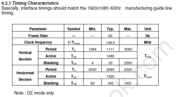
1.      The below is the panel timing  has ever enabled our target panel to work in other bridge IC( LVD-to-eDP bridge )

Resolution = 1920x1080

vertical_sync_active = 2

vertical_backporch = 4

vertical_frontporch = 2

horizontal_sync_active = 18

horizontal_backporch = 50

horizontal_frontporch = 50


2.      The panel does not support ASSR mechanism.

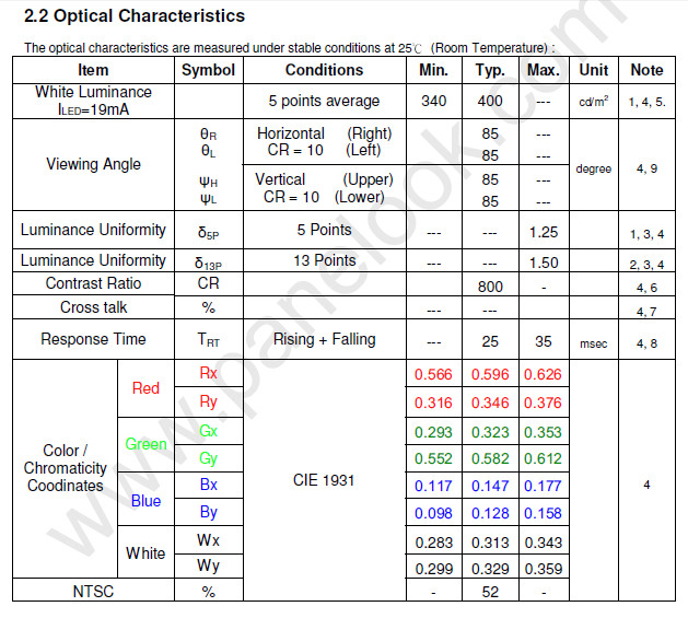
3.      The data format input to the panel is RGB 666.


  • Hello Herry,

    Please, share the schematics and a dump file of the DSI86 registers.

    Regards
  • Hi Joel,

    Please find schenatics as attachment and refer below message by my customer shared.

    ============================================================================================================

    The attached file is our schematics of our own development board,

    of which REFCLK FREQUENCY is 26 MHz.

    Unfortunatly, its TEST2 pin is always pulled low, which will cause non-ASSR mode can not be supported.

    But we will have a new development board of which TEST2 pin with a resistance is pulled high by default.

    Anyway, our team recently got SN65DSI86/96 EVM from TI,

    and we connected the I2C related pins on our own development board  to the I2C related pins  of the bridge IC on SN65DSI86/96 EVM in order to issue I2C commands to configure bridge IC on SN65DSI86/96 EVM of which REFCLK FREQUENCY is 27 MHz.

    I set the register 0x3C to be 0x10 to enable test patern(color bar) and used the setting sent by you  yesterday to support our target panel not supporting ASSR mechanism.

    (I  also downloaded the user manual of SN65DSI86/96 EVM from   )

    The error of of the interrupt status registers were retrived as the following.

    The error value of the register 0xF0 is 0x01.

    The error value of the register 0xF1 is 0x09.

    The error value of the register 0xF8 is 0x02.

    Besides providing us with a valid script  for SN65DSI86/96 EVM to output a test patten based on the panel timing and data format(RGB666) I provided yesterday,

    please provide us with another valid script for our own development board which will really supply MIPI data to SN65DSI86 bridge.

    In this way, after TEST2 pin of our own development board is corrected, I can soon try the setting from TI.

    ============================================================================================================

    SCHEMATIC1 _ 17_eDP.PDF

  • scripts_DSI86.zipHello Henry,

    Attached are some scripts that you can use as an reference to enable the test pattern mode with a 1920x1080 panel. Please, also refer to the EVM users guide to set up the EVM correctly .

    Make sure TEST2 pin is high at rising edge of EN

    Regards

  • Hi Joel,

    My customer have followed your advices and still got failure result.

    The error value of register 0xF1 is 0x0B,

    And The error value of register 0xF8 is 0x0x12,

    Which were caused by using the script provided by you.

    So, we stiil need you to provide other adivces. Thanks!

  • Could you provide the latest register dump?

    Regards,
    Joel