This thread has been locked.

If you have a related question, please click the "Ask a related question" button in the top right corner. The newly created question will be automatically linked to this question.

DP83867IR: Auto negotiation result in 100M while the advertise ability is set to 10/100/1000M. Ethernet cable cannot be found when some adapters

Part Number: DP83867IR
Other Parts Discussed in Thread: LP5912

Hello,

We have circuit board with a DP83867IRPAP on it. It is connected to a FPGA, which will provide the MAC. The MAC is not implemented yet. We have got some difficulties in making our PHY work so I was wondering if anyone here can offer some advice.

RX_DV/CTRL is configured to strap mode 3 so auto-negotiation is enabled. RX_D4 and LED_1 are both configured to strap mode 1 so the advertise ability is set to 10/100/1000M (ANEG_SEL1=1, ANEG_SEL0=0). All other strap pins are configured to mode 1 except pin RX_D6, which is in mode 3 to disable RGMII interface. 

The power supplies, RBIAS and the resistor connected to it are all checked and they all have the expected values. The strap pins are also checked while reset_n is held low, and the voltages are as expected. 

We have two problems here:

1. when the board is connected to PC and the Ethernet cable is recognized, the established speed is 100M instead of 1000M. The speed of the Ethernet adapter of the PC is set to auto-negotiate too. So I think this means the auto-negotiation failed? I tried different Ethernet cables all resulted in 100Mbps. Can anyone provide some insight on what the cause is and how to get it fixed?

2. I tried the board with six different computers, 100Mbps connection can be established with 4 of them, the other two indicated that there was no Ethernet cable. It happened that the two computers both have Intel Ethernet adapter. Is it a issue of compatibility ? Or is it just a coincidence?  What could be the cause to the different results while using different computers?

Thank you!

Lingmei

  • Hi,

    Kindly shared the value of following registers.

    -0x00, 0x01, 0x006E, 0x006F


    Regards,
    Geet
  • Hi Geet,

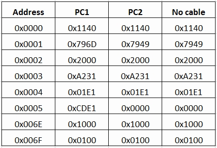
    I tried to read the registers with the address 0x0000, 0x0001, 0x0002, 0x0003, 0x0004, 0x0005, 0x006E and 0x006F when the board is connected to PC1 (100Mbps connection established), PC2(no connection) and no PC. The value of the registers are:

    Edit: To add few more registers here (This is when the 100M connection is established):

    Address

    Data

    0x0009

    0x0300

    0x000A

    0x0800

    0x0014

    0x29C7

    0x0017

    0x0040

    0x0018

    0x6150

    0x0019

    0x4444

    0x001A

    0x0002


    According to the value of register 0x006E, the straps are the same as the settting on the board: auto-negotiation enabled, RGMII disable, speed at 10/100/1000M. Bit 8 of register 0x006F is different from the default value, is it normal?

    Also, the registers have the same values when the Ethernet cable is PC2 or nothing, what could be the cause that PC2 cannot be recognized?

    Thanks you!

    Lingmei

  • Hi,

    Looked at the strap configuration settings and looks ok.

    For PC2 : Auto Negotiation is not going thru. Phy do not have Auto-Neg Capabilities of LP ( Register 0x0005).

    Did you try connecting DP83867 with other DP83867. Does link come up in 1000M mode with same cable ?

    Also, I would like to see value of register 0x0011, 0x001E as well. Also, you may try enabling Robust Auto MDI-X in 0x001E and Mirror ( in case the ports are swapped) as well.

    Regards,
    Geet
  • Hi Geet,

    Thanks for your suggestions. 

    For PC2, auto-negotiation was enabled in the settings. When it was connected to another board (let's call it board 0) using another PHY, 1Gbps link could be established. 1Gbps link could also be established when board0 is connected to PC1. No connection can be established between our DP83867 board and board2.

    I am going to get another board with DP83867 and see if the two identical board can establish a good link. I will update you with the result later. (Edit: done, results given below)

    The data read from 0x0011 is 0x7F02 (0x6F02 if it is read again because bit 12 is cleared upon read). So it says the link speed is 100Mbps. Since previous data read from the registers showed that both the board and the PC have the capability of 1000Mbps link, what else could cause it result in 100M after auto-negotiation?

    The data read from 0x001E is 0x0002. I enabled Robust Auto MDI-X by writing 0x0202 to register 0x001E, then restart auto-negotiation by writing 0x1340 to register 0x0000, it still resulted in 100Mbps connection.

    To enable Mirroring, without changing straps, I decided to write to register 0x0031. The value read from it after reset is 0x00B0, but according to the data sheet, it should be 0x0010, is this a problem? Anyway, I tried to enable mirroring by writing 0x0011 or 0x00B1, in both cases, the connection is lost immediately after the writing operation, restarting auto-negotiation dose not get any connection. Then I tried to write 0x0010 (default value according to the datasheet) or 0x00B0 (data read from it after reset), the connection is also lost upon writing operation. Since most of the bits in register 0x0031 are reserved, I don't know why a writing operation affected the link status, could you give more insights?

    If not by writing to 0x0031, I need to strap LED0 to mode 3, but the datasheet only gives examples about mode 1 and mode 4, I am not sure if my understanding of setting it to mode 2 and mode 3 is correct. Could you let me know the connections in the figure attached is correct?

    Edit: I connected two boards and the link could not be established between the two (no LED was on). Both boards can have 100M link with a PC, most of the registers have the same value except register 0x11, one of them is 0x7F02 the other is 0x7C02. I was wondering what could be the cause to the difference. 

    When the two boards are connected, the value read from register 0x11 could be 0x1102, 0x1202, 0x1302, 0x1002 or 0xB202, it seems random. When the reading is 0xB202, reading it again later will return with other values other than [bit15, bit14] = 10, so this 1000Mbps connection seems not valid. The table below lists the values of the registers in different circumstances. 

    Address Board1 (connected to B2) Board2 (connected to B1) Board1 (connected to PC) Board2 (connected to PC)
    0x00 0x1140 0x1140 0x1140 0x1140
    0x01 0x7949 0x7949 0x796D 0x796D
    0x02 0x2000 0x2000 0x2000 0x2000
    0x03 0xA231 0xA231 0xA231 0xA231
    0x04 0x01E1 0x01E1 0x01E1 0x01E1
    0x05 0xC1E1 0xC1E1 0xCDE1 0xCDE1
    0x09 0x0300 0x0300 0x0300 0x0300
    0x0A 0x0C00 0x0C00 0x0800 0x0800
    0x0F 0x3000 0x3000 0x3000 0x3000
    0x11 0x1002 0x1202 0x7F02 0x7C02
    0x14 0x29C7 0x29C7 0x29C7 0x29C7
    0x1E 0x0002 0x0002 0x0002 0x0002
    0x1F 0x0000 0x0000 0x0000 0x0000
    0x31 0x00B0 0x00B0 0x00B0 0x00B0
    0x6E 0x1000 0x1000 0x1000 0x1000
    0x6F 0x0100 0x0100 0x0100 0x0100

    Thanks a lot.

    Lingmei

    8321.LED_mode2_mode3.tif

  • Hi,

    I also tried similar experiment today to connect a DP83867 EVM with PC. Tried both Auto-Neg and 1GB configuration on PC and could get the link up. Registers values seems to be similar what you are observing excluding status register for link-up the 0x000A (7800), 0x0011 ( BC02), 0x006E ( 8820)

    Even no link between two DP83867 is surprising, Can you check the XTAL clock quality, board layout etc are ok ?

    Regards,
    Geet
  • Hi Geet,

    Thank you for doing the experiment for comparison. 

    Just to confirm, no programming is needed for the PHY to establish a link with PC, is it correct? 

    In your case, for  register 0x0011, bit 9 and bit8 are both 0, but in my case, one of my boards have both 1 and the other have both 0. How is this register determined? For register 0x006E, I noticed that mirroring and RGMII are strapped to enable (both disable in my case), and speed is set to 1000Mbps (mine is 10/100/1000), could this result in different auto-negotiation results? Previous I tried to enable mirroring by in that case, even 100M connection could not be established. I also tried to set the speed to only 1000Mbps, no connection could be established either. 

    I checked the quality of the XTAL clock,  and the screen is attached.  The blue trace is the clock on pin 18 and the  green one is on pin 19. There is a little bit distortion on pin18, could this be a problem?

    I have two more questions: 

    1. I read the value of register 0x0004 (0x01E1) and 0x0005(0xCDE1), so bit15 of register 0x0004 says next page transfer is not desired, while bit15 of  0x0005 says link partner desires next page transfer. It seems a conflict, is it because the setting of the PHY is not correct, or it is just because the auto-negotiation is not successful ?I tried to enable bit 15 of 0x0004 but after that no link could be established when a restart auto-negotiation. 

    2. The 1.1V voltage for pin 8/29/42/58 is generated by IT LP5912, is it suitable for this application?  I probed the voltages on the power supply pins and found that they all have some small ripples, the peak-to-peak value is around 30mV expcept for pin23, which is 50mV (figure attached), could this cause the problem?

    3. Found another problem. According to the datasheet, pin22 is an output clock synchronized with the XI oscillator. This feature is set to 'enable' (register 0x6E has value of 0x1000), and the reading from register 0x0170 is 0x0C0E. But no clock is detected on pin22 instead of a quite strange weak signal (as attached). Did I misunderstand it? Or it means there is something wrong with the board?

     B4_Pin22_CLK_OUT.tif)

    I will ask my college who designed the board to check the layout as I am not familiar with it.

    Thank you!

    Lingmei

     7380.B3_Pin23_PHY_VDD2V5z.tif

    5732.B3_X1_25MHz.tif

  • register 0x0011 : Auto Negotiation shall resolved to really interpre these value. We can ignore them till.

    register 0x006E : On my board, SGMII was strapped hence difference. It shall not interfere with Auto-Neg. Changing Mirroring, you already tried and it's not helping. Speed setting is also ok.

    XTAL : Important is ppm of the clock. Alternatively, if you have good quality clock source, you can try injecting the 25 Mhz from that.

    Power Supply : Please refer to DP83867 Troubleshooting guide and ensure you have followed the guidelines for de-caps. http://www.ti.com/lit/an/snla246a/snla246a.pdf

    Clock OUtput : Yes, DP83867 provides capability to output the various clocks ( XTAL, derived) and you shall see the clock output on the pin.

    Regards,
    Geet

  • Hi Geet,

    I compared our design with the recommended power supply in the troubleshooting guide and found that 0.01uF was used instead of one of the 0.1uF capacitors. I will get this fixed once we receive the capacitors. But the voltages measured on the pins are in the range given in the datasheet, so I guess the requirement is met? For the layout, I was wondering if you could help to have a look at our layout files (attached, U22 is the PHY).

    One more questions, if we want to purchase an evaluation card of DP83867, will this one work (www.ti.com/.../dp83867irpap-evm )? What did you use in your tests?

    Thanks a lot.

    Lingmei pcb.zip

  • Hi Geet,

    I was wondering if you had chance to have a look at my previous questions. Thanks a lot.

    Lingmei
  • Hi,

    Can you share the schematics of the Phy as well ?

    Yes, you can purchase online. We have two version 48pin and 64 pin. You can choose based on what you are using on your design.

    Regards,
    Geet

  • Hi Geet,

    The schematics are attached. Thanks a lot!

    Lingmei

    PCB_6V130T_Full.pdf

  • Hi Lingmei,

    Looked at your schematics. One thing I noticed that Magnetics/RJ-45 used is from Hello( RJ45_HFJ11-1G01E) .

    www.mouser.com/.../fastjack-gigabit-520265.pdf

    Per this model, it's suitable for current mode Line driver. However DP83867 is based on Voltage Line Driver as mentioned in DP83867 Troubeshooting Guide ( http://www.ti.com/lit/an/snla246a/snla246a.pdf 

    Can you try the other part from Hello suitable for Voltage line driver. I think HFJ11-1G4 series shall be ok.

    Regards,
    Geet

  • Hi Geet,

    Thanks a lot for your help. We will get compatible RJ45 to replace the current one and see if everything turns out OK.

    Regards,

    Lingmei

  • Hi Geet,

    I bought a HFJ11-1G41ERL and replaced the previous RJ45, now there is 1Gbps connection.

    Thanks for your help!

    Lingmei

  • Nice to hear that !!

    Thanks,
    Geet