This thread has been locked.

If you have a related question, please click the "Ask a related question" button in the top right corner. The newly created question will be automatically linked to this question.

DS90UB921-Q1: Display works with Internal clock , but not with external clock

Part Number: DS90UB921-Q1
Other Parts Discussed in Thread: DS90UH948-Q1, ALP

Hi, 

For our custom display solution, we are using the below serdes pair

Serializer : DS90UB921-Q1 

Deserializer : DS90UH948-Q1

Display timings are configured properly in the kernel.

But we do not get anything up on the display. 

serdes lock is established.

Serializer test patterns and deserializer test patterns also do not work with external clock timings.

Work-around:

If we run serializer pattern with internal clock, then we see that the pattern is coming on the display.

Later if we disable the pattern, then our HMI is up on the display.

Need support here to understand what configuration is set on serializer/de-serializer when we set the internal clock pattern ?

Note : we see only register 0x3B getting updated on deserializer side between working and non-working scenarios. This register has no mention in datasheet, seems to be reserved one. 

  • Pradeep,
    Please note that this e2e post has been assigned to the appropriate expert.
    John G.
  • Hello Pradeep,

    Firstly, Reg 0x3B is the EQ status register, and it makes sense that 0x3B may change when the input signal changes.

    How did you configure the pattern generator? Did you configure it by Analog Launch Pad or by scripts? If you use ALP, could you post the capture of PG setup? If you use scripts, could you upload the script?

    The external video timing means the control signals (HS, VS, DE) are external, so you should provide external timing, or you may use internal video timing by setting PATGEN_TSEL to 1.

    Here's an application note for pattern generator for your reference: www.ti.com/.../snla132c.pdf

    Best regards,
    Cera
  • Hi Cera,

    Pattern generator was configured using i2c channel using register 0x65 on serializer
    i2cset -f -y 1 0x0c 0x65 0x01
    i2cset -f -y 1 0x0c 0x64 0x11

    The external timings are configured in kernel and all timings : Clk, Hsycn, VSync, DE , front porch and back porch are configured through kernel.
    we are using DRA74x based SoC with Ti PSDK 3_03.

    For working case as mentioned in my last post, we used the internal clock using Pattern Generator Timing Select of 0x65 register.

    I would like to understand why the display isn't working with external timings alone, but works when we first set internal timing through pattern and then disable the pattern.
  • Hello Pradeep,

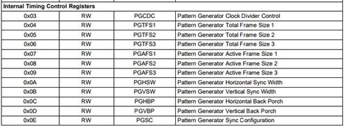
    Could you upload the register dumps (regular registers and the pattern generator indirect data registers) of the two cases:

           1. the failed case that use external timing alone

           2. the working case that first use internal timing and then disable the pattern. 

    By the way, what's the resolution, the frame rate and pixel frequency of your input signal? 

    Best regards,

    Cera

  • Hi Pradeep,

    The two conditions you mentioned should be the same. Did you use the same pattern for test? What pattern did you use? Could you try to use color bar pattern?

    What do you mean by saying doesn't work? Is this black screen?

    Could you check the HS, VS, DE requirement of your panel and make sure your timing setup is right?

    Best regards,
    Cera
  • Hi  Cera, 

    I have attached file for register dumps (regular registers and the pattern generator indirect data registers) of the two cases.

     1. the failed case that use external timing alone

     2. the working case that first use internal timing and then disable the pattern. 

    Resolution : 800*480

    Frame rate : 60

    Pixel frequency : 2.54 MHz

    mGED-issue-Cera-TI.txt
    Fullscreen
    1
    2
    3
    4
    5
    6
    7
    8
    9
    10
    11
    12
    13
    14
    15
    16
    17
    18
    19
    20
    21
    22
    23
    24
    25
    26
    27
    28
    29
    30
    31
    32
    33
    34
    35
    36
    37
    38
    39
    40
    41
    42
    43
    44
    45
    46
    47
    48
    49
    50
    51
    52
    53
    54
    55
    56
    57
    58
    59
    60
    61
    62
    63
    64
    65
    66
    67
    ==================================================================================================================================================
    NON-WORKING CASE - EXTERNAL TIMING
    ==================================================================================================================================================
    root@mmt:~# i2cdump -y -f 1 0x0C
    No size specified (using byte-data access)
    0 1 2 3 4 5 6 7 8 9 a b c d e f 0123456789abcdef
    00: 18 00 00 ab 8a 00 78 00 00 00 00 00 05 00 00 00 ?..??.x.....?...
    10: 00 00 0a 10 00 00 fe 5e a1 a5 00 00 00 00 00 00 ..??..?^??......
    20: 00 00 25 00 00 00 00 00 00 24 00 a0 00 00 00 00 ..%......$.?....
    30: 03 10 00 00 00 00 08 34 00 0a 20 21 00 00 f0 00 ??....?4.? !..?.
    40: 00 00 00 00 00 00 00 00 00 00 00 00 00 00 00 00 ................
    50: 20 00 00 00 00 00 00 00 00 00 00 00 00 00 00 00 ...............
    60: 00 00 00 00 10 00 03 08 00 00 00 00 00 00 00 00 ....?.??........
    70: 00 00 00 00 00 00 00 00 00 00 00 00 00 00 00 00 ................
    80: 00 00 00 00 00 00 00 00 00 00 00 00 00 00 00 00 ................
    90: 00 00 00 00 00 00 00 00 00 00 00 00 00 00 00 00 ................
    a0: 00 00 00 00 00 00 00 00 00 00 00 00 00 00 00 00 ................
    b0: 00 00 00 00 00 00 00 00 00 00 00 00 00 00 00 00 ................
    c0: 00 00 80 00 68 08 00 00 40 00 00 00 00 00 00 00 ..?.h?..@.......
    d0: 00 00 00 00 00 00 00 00 00 00 00 00 00 00 00 00 ................
    e0: 00 00 00 00 00 00 00 00 00 00 00 00 00 00 00 00 ................
    f0: 5f 55 42 39 32 31 00 00 00 00 00 00 00 00 00 00 _UB921..........
    root@mmt:~# i2cset -f -y 1 0x0C 0x66 0x03
    root@mmt:~# i2cget -f -y 1 0x0C 0x67
    0x08
    root@mmt:~# i2cset -f -y 1 0x0C 0x66 0x04
    root@mmt:~# i2cget -f -y 1 0x0C 0x67
    0x48
    root@mmt:~# i2cset -f -y 1 0x0C 0x66 0x05
    root@mmt:~# i2cget -f -y 1 0x0C 0x67
    0x53
    root@mmt:~# i2cset -f -y 1 0x0C 0x66 0x06
    root@mmt:~# i2cget -f -y 1 0x0C 0x67
    0x1e
    root@mmt:~# i2cset -f -y 1 0x0C 0x66 0x07
    root@mmt:~# i2cget -f -y 1 0x0C 0x67
    0x20
    root@mmt:~# i2cset -f -y 1 0x0C 0x66 0x08
    root@mmt:~# i2cget -f -y 1 0x0C 0x67
    0x03
    root@mmt:~# i2cset -f -y 1 0x0C 0x66 0x09
    root@mmt:~# i2cget -f -y 1 0x0C 0x67
    0x1e
    root@mmt:~# i2cset -f -y 1 0x0C 0x66 0x0A
    root@mmt:~# i2cget -f -y 1 0x0C 0x67
    0x0a
    root@mmt:~# i2cset -f -y 1 0x0C 0x66 0x0B
    root@mmt:~# i2cget -f -y 1 0x0C 0x67
    0x02
    root@mmt:~# i2cset -f -y 1 0x0C 0x66 0x0C
    root@mmt:~# i2cget -f -y 1 0x0C 0x67
    0x0a
    root@mmt:~# i2cset -f -y 1 0x0C 0x66 0x0D
    root@mmt:~# i2cget -f -y 1 0x0C 0x67
    0x02
    root@mmt:~# i2cset -f -y 1 0x0C 0x66 0x0E
    root@mmt:~# i2cget -f -y 1 0x0C 0x67
    0x03
    ==================================================================================================================================================
    WORKING CASE - INTERNAL TIMING - PATTERN ENABLED AND THEN DISABLED
    ==================================================================================================================================================
    XXXXXXXXXXXXXXXXXXXXXXXXXXXXXXXXXXXXXXXXXXXXXXXXXX

  • Hi Cera,

    yes, Same pattern for testing. I used pattern with autoscroll enabled through 0x65. None of pattern work with external timings

    Doesnt work means nothing on display => Blank screen

    HS , VS and DE and proper, these are working on another variant with J6Entry SoC.
  • Hi Pradeep,

    I have checked the register dump, there's nothing wrong. The internal timing should be turned off when you turn off the pattern generator. Could you check:

    1. The pulse width should has restriction as blow. Reg. 0x03 on 921 says the control signal filter is disabled, so DS and HS has no restriction, but VS pulse width should be more than 130 clock cycles. You should also check Reg.0x03 bit4 on 948 to check the control signal filter and restrictions.  Could you show me your DE, HS and VS timing?

    2. If the VS timing meets the requirement but it still doesn't work, could you check the output of the LVDS? Could you see if there's nothing output or just failed to display? 

    Best regards,

    Cera

  • Hi Cera,

    1. Below are the timings, this is as per the datasheet from Display vendor. As I said the below timings works fine with another variant using J6 Entry SoC.

    clock-frequency = <25400000>;
    hactive = <800>;
    vactive = <480>;

    hfront-porch = <32>;
    hback-porch = <32>;
    hsync-len = <2>;

    vfront-porch = <5>;
    vback-porch = <5>;
    vsync-len = <2>;

    hsync-active = <1>;
    vsync-active = <1>;
    de-active = <1>;
    pixelclk-active = <1>;

    2. A little background here :
    we are currently testing with 2 kind of display
    a. Actual display unit with TFT from vendor ==> On this the above timings are working proper.
    b. Generic display adaptor that can convert LVDS to HDMI and display on HDMI Monitor ==> On this we face the issue as described in original mail thread.

    Hence the LVDS signal out is proper.
    Ideally we expect both above display to work since there is not other change. This is working for other variant (J6 Entry) with same display.
  • Hello Pradeep,

    The timing looks fine for fpd-link parts.

    The other thing, does the LVDS to HDMI adapter require HDCP? 921 is UB part, so it can't give out HDCP, which may cause no output on adapter.

    Best regards,

    Cera

  • Hi Cera,

    LVDS to HDMI does not need HDCP.
    With same serializer 921 on J6Entry variant, and same adapter , we get the output on monitor.

    Any other suspicion is helpful, we need to get a solution for this at the earliest.
  • Hi Pradeep,

    Here's the summary of the issue, if there's something I left out, please fill in, thanks.

    Issue: J6 Entry - 921 - 948 - LVDS to HDMI adapter - display doesn't work, black screen

    Work around:

    √ Pattern generator with internal timing - 921 - 948 - adapter - display

    x Pattern generator with external timing - 921 - 948 - adapter - display

    x Different pattern with external timing

    Suspect control timing is wrong:

    √ Checked HS, VS, DE, they all larger than 130 pclk

    √ J6 Entry - 921 - 948 - display (from vendor): prove the timing works properly on the display

    ( This is from your description: Actual display unit with TFT from vendor ==> On this the above timings are working proper. What's the difference between this setup and the one that doesn't work?)

    Suspect the adapter's fault:

    √ J6Entry variant - 921 - 948 - adapter - display

    (With same serializer 921 on J6Entry variant, and same adapter , we get the output on monitor, What's the difference between this setup and the one that doesn't work?)

    √ Checked the HDCP, no HDCP required from the adapter

    Could you check the following things:

    1. Set the pattern generator to the same timing with the external timing. You can go to indirect pattern generator register to set the timing, for more details, please refer to application note: http://www.ti.com/lit/an/snla132c/snla132c.pdf. If it works, we can thoroughly exclude the timing's fault.

    2. What's the specific setup you mentioned in your previous mail?

    a. Actual display unit with TFT from vendor ==> On this the above timings are working proper. Is this: J6 Entry - 921 - 948 - (LVDS) display (from vendor)? The difference is there's no LVDS - HDMI adapter and the display is LVDS input?

    b. With same serializer 921 on J6Entry variant, and same adapter , we get the output on monitor. Is this: J6Entry variant - 921 - 948 - adapter - display?  What's the difference between this setup and the one that doesn't work?

    c. The LVDS output from 948 is correct ( the LVDS displays properly) but there's no signal output from the adapter? All the HDMI data output is 000000? 

    Best regards,

    Cera

  • Hi Cera,

    We found an issue with our timing and fixed it.
    Thanks for the help.

    Regards,
    Pradeep