This thread has been locked.

If you have a related question, please click the "Ask a related question" button in the top right corner. The newly created question will be automatically linked to this question.

DP83620: AM4377 Ethernet packet loss

Part Number: DP83620
Other Parts Discussed in Thread: AM4377, , DP83640

Hi,

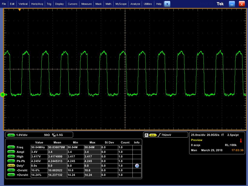
We are using TI's AM4377 CPU and DP83620 Ethernet PHY in one of our projects. We are able to make 10 Mbps up, but with 100 Mbps there is around 30-60% packet loss. Our test set-up is as below.
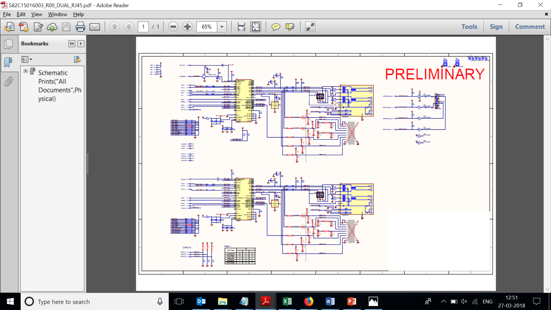
AM4377 CPU located in the main PCB and DP83620 Ethernet PHY in the communication PCB. CPU/MAC to PHY connection is through Samtec card edge connector (PN: HSEC8-120-01-SM-DV-A). Attached Ethernet PHY board schematics herewith. The trace lengths are within DP83620 PHY guidelines (< 6 inches as in 'AN-1469 PHYTER Design & Layout Guide'). Attached Trace length details as well.

Also, please find few more queries:

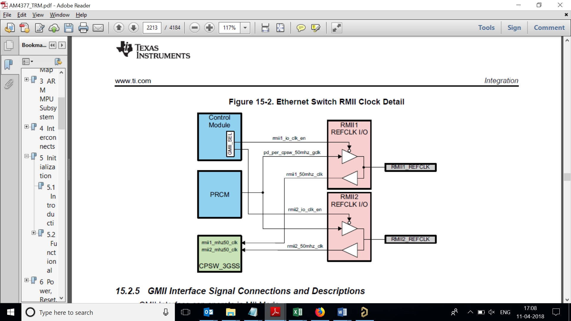
  • Please let us know the strap option for TX 6558.ETHERNET_LENGTH_MATCH_ANALYSIS_TI.xlsxD_3 pin (to enable RMII Slave mode), as it is not clear from datasheet.
  • Request your suggestion in finding the right termination value for these trace lengths and any other recommendations if any (other than termination resistor).
  • We did not get any errata sheet for the PHY chip. Please help on this as well.


Best Regards,
Madhusoodana Bairy

  • Hi Madhusoodana,

    If you are having problems with packet errors, the problem is usually related to the reference clock's jitter.

    The AM335x has a KNOWN jitter issue which means it cannot be used to provide the RMII reference to an external RMII phy. This may also apply to the AM437x family.

    I am moving this to the AM437x forum.

    Best Regards,
  • Hi Rob,

    Thanks for your reply.

    Clock to the PHY we are sourcing from an external oscillator and we are not using reference clock from the processor (though we have provided option, we have unmounted R41&R42 series resistors in the schematics).

    Please suggest.

    Best Regards,

    Madhusoodana Bairy

  • Hello Madhusoodana,
    Did you perform a timing analysis of the interface prior to layout?

    RMII has very tight timing constraints so the interface timing of your MAC+PHY must be well understood beforehand. To be clear, I'm not referring to trace-length matching, I'm referring to the interface setup/hold/delay timing. Each MAC and PHY has different timing constraints, so a timing analysis is required.
  • Hi DK,

    Whether RMII reference clock is input to the MAC or output from the MAC ? Because, as per DP83620 datasheet, it is input to the MAC and required only in RMII master mode. And as per TI AN-1405 (SNLA076A), it is O/P from MAC. Could you please clarify on this, as different silicon vendors use this in different ways. Because, we are seeing that 50MHz clock's amplitude is varying from around 2V to 3.3V (oscillator clock we are sourcing to both PHY and MAC). Currently we have configured this as input to processor. If it not so, our design is wrong, as we are giving oscillator clock to MAC (my comment in earlier post that, "Clock to the PHY we are sourcing from an external oscillator and we are not using reference clock from the processor", is wrong).

    We are running out of time. So requesting you to reply asap.
    We will do timing analysis once these configurations are cleared.

    Best Regards,
    Madhusoodana Bairy

  • Madhusoodana,
    It sounds like you have the clock topology right from an SoC perspective.

    The AM437x SoC cannot source the RMII 50MHz REF_CLK. This pin must be properly set as an input in your pinmux and then supplied with a low-jitter clock from an external device. Typically this 50MHz clock is shared by the MAC and the PHY, with attention given to equalizing the trace-length from CLOCK-MAC and CLOCK-PHY as doing so ensures that both MAC and PHY share the same clock timing.
  • Hi DK,

    Interestingly, we are seeing a 50MHz clock from SoC pin! We have isolated communication PCB (where PHY and RJ45 connector are located) & we are able to see the clock in processor board itself. But the problem is, if we disable this pin in software (to use oscillator clock), then PHY address is not getting detected. But if we simply isolate processor clock to PHY (by cutting trace), it works but 20-35% packet loss is there. Please help on this.

    Attached oscilloscope captures of Oscillator clock & Clock from SoC.

    Best Regards,
    Madhusoodana Bairy

  • Madhusoodana,
    The MAC appears to be (incorrectly) set in Clock-Out mode. Please verify that your Device Tree is setting RMII Clock-In Mode. This can be verified in HW by reading the CTRL_GMII_SEL register (Page 689 of Rev H TRM).

    If this is wrong, I think it likely that your pinmux mode/pad config selections for RMII REF_CLK are also incorrect. Please double-check these.
  • Hi,

    Could you please attach (not cut and paste) the DTS file for your board? If you prefer not attach the board DTS please attach the portions related to networking such as the mac node definitions and pin mux definitions. Also please attach patches to any system include dtsi files that have been modified. And finally please attach a patch of any files modified in this directory of the kernel drivers/net/ethernet/ti/

    Best Regards,

    Schuyler

  • Hi DK/Schuyler,

    Sorry for the delay in response. The delay was because we found some improvement in our testing. We have added 33 ohm series termination resistor to processor clock (MAC to PHY clock) and tested internal and external loopbacks and we found that there is no packet loss in these 2 tests. But if we connect to network, there is 30-40 % packet loss. I think when we have enabled loopbacks, it is working in border condition & to work with network, it needs to have proper/better timing requirements. Please suggest.

    I will share the DTS file shortly.

    Best Regards,

    Madhusoodana Bairy

  • Madhusoodana,
    Above you say "MAC to PHY clock". Could you please clarify? As I mentioned earlier in this thread, the MAC cannot source the 50MHz RMII clock.
  • Hi DK/Schuyler,

    We are see

          ethernet_phy_pins_default: ethernet_phy_pins_default {                   
                    pinctrl-single,pins = <                                          
                    /* phy 1 */                                                      
                            AM4372_IOPAD(0x90c, PIN_INPUT_PULLDOWN | MUX_MODE1 )  /* (B14) mii1_crs.rmii1_crs_dv */
                            AM4372_IOPAD(0x910, PIN_INPUT_PULLDOWN | MUX_MODE1 )  /* (B13) mii1_rx_er.rmii1_rxer */
                            AM4372_IOPAD(0x914, PIN_OUTPUT_PULLDOWN | MUX_MODE1 ) /* (A13) mii1_tx_en.rmii1_txen */
                            AM4372_IOPAD(0x924, PIN_OUTPUT_PULLDOWN | MUX_MODE1 ) /* (A14) mii1_txd1.rmii1_txd1 */
                            AM4372_IOPAD(0x928, PIN_OUTPUT_PULLDOWN | MUX_MODE1 ) /* (B15) mii1_txd0.rmii1_txd0 */
                            AM4372_IOPAD(0x93c, PIN_INPUT_PULLDOWN | MUX_MODE1 )  /* (B16) mii1_rxd1.rmii1_rxd1 */
                            AM4372_IOPAD(0x940, PIN_INPUT_PULLDOWN | MUX_MODE1 )  /* (F17) mii1_rxd0.rmii1_rxd0 */
                            AM4372_IOPAD(0x944, PIN_INPUT_PULLDOWN | MUX_MODE0 )  /*(A16) rmii1_ref_clk.rmii1_refclk*/
                                                                                     
                    /* phy 2 */                                                      
                            AM4372_IOPAD(0x840, PIN_OUTPUT_PULLDOWN | MUX_MODE3 ) /* (C3) gpmc_a0.rmii2_txen */
                            AM4372_IOPAD(0x850, PIN_OUTPUT_PULLDOWN | MUX_MODE3 ) /* (D7) gpmc_a4.rmii2_txd1 */
                            AM4372_IOPAD(0x854, PIN_OUTPUT_PULLDOWN | MUX_MODE3 ) /* (E7) gpmc_a5.rmii2_txd0 */
                            AM4372_IOPAD(0x86c, PIN_INPUT_PULLDOWN | MUX_MODE3 )  /* (D8) gpmc_a11.rmii2_rxd0 */
                            AM4372_IOPAD(0x868, PIN_INPUT_PULLDOWN | MUX_MODE3 )  /* (G8) gpmc_a10.rmii2_rxd1 */
                            AM4372_IOPAD(0x870, PIN_INPUT_PULLDOWN | MUX_MODE3 )  /* (A2) gpmc_wait0.rmii2_crs_dv */
                            AM4372_IOPAD(0x874, PIN_INPUT_PULLDOWN | MUX_MODE3 )  /* (B3) gpmc_wpn.rmii2_rxer */
                            AM4372_IOPAD(0x908, PIN_INPUT_PULLDOWN | MUX_MODE1 )  /* (D16) mii1_col.rmii2_refclk */
                    >;                                                               
            };                                                                       
                                                                                     
            davinci_mdio_default: davinci_mdio_default {                             
                    pinctrl-single,pins = <                                          
                            /* MDIO */                                               
                            AM4372_IOPAD(0x948, PIN_INPUT_PULLUP | SLEWCTRL_FAST | MUX_MODE0)       /* mdio_data.mdio_data */
                            AM4372_IOPAD(0x94c, PIN_OUTPUT_PULLUP | MUX_MODE0)                      /* mdio_clk.mdio_clk */
                    >;                                                               
            };                                                                       
                                                                                     
            davinci_mdio_sleep: davinci_mdio_sleep {                                 
                    pinctrl-single,pins = <                                          
                            /* MDIO reset value */                                   
                            AM4372_IOPAD(0x948, PIN_INPUT_PULLDOWN | MUX_MODE7)      
                            AM4372_IOPAD(0x94c, PIN_INPUT_PULLDOWN | MUX_MODE7)      
                    >;                                                               
            };


    &mac {                                                                           
            status = "okay";                                                         
            pinctrl-names = "default";                                               
            pinctrl-0 = <&ethernet_phy_pins_default>;                                
            /* for SK EVM pinctrl-0 = <&cpsw_default>;*/                             
            /* for SK EVM pinctrl-1 = <&cpsw_sleep>;*/                               
            slaves = <2>;                                                            
            dual_emac;                                                               
    };                                                                               
                                                                                     
    &davinci_mdio {                                                                  
            pinctrl-names = "default", "sleep";                                      
            pinctrl-0 = <&davinci_mdio_default>;                                     
            pinctrl-1 = <&davinci_mdio_sleep>;                                       
            status = "okay";                                                         
    }; 
    
    ing 50MHz clock on RMII_REFCLK even if we have configured it as input! I have attached DTS file. We did not modify anything in the driver.

    Also, can you please suggest what we have to set in the following fields:

    DS0 mode in CTRL_CONF_RMII1_REFCLK Register Field (bits 24-28) (all 0 now)

    CONF_RMII1_REFCLK_RXACTIVE & CONF_RMII1_REFCLK_MMODE bits in CTRL_CONF_RMII1_REFCLK Register (both are 0 now)

    RMII1_IO_CLK_EN in CTRL_GMII_SEL register (0 now)

    Best Regards,

    Madhusoodana Bairy

  • Hi DK/Schuyler,

    We are observing 50MHz clock on RMII_REFCLK even if we have configured it as input! I have attached DTS file. We did not modify anything in the driver.

    Also, can you please suggest what we have to set in the following fields:
    DS0 mode in CTRL_CONF_RMII1_REFCLK Register Field (bits 24-28) (all 0 now)
    CONF_RMII1_REFCLK_RXACTIVE & CONF_RMII1_REFCLK_MMODE bits in CTRL_CONF_RMII1_REFCLK Register (both are 0 now)
    RMII1_IO_CLK_EN in CTRL_GMII_SEL register (0 now)

    Best Regards,
    Madhusoodana Bairy

          ethernet_phy_pins_default: ethernet_phy_pins_default {                   
                    pinctrl-single,pins = <                                          
                    /* phy 1 */                                                      
                            AM4372_IOPAD(0x90c, PIN_INPUT_PULLDOWN | MUX_MODE1 )  /* (B14) mii1_crs.rmii1_crs_dv */
                            AM4372_IOPAD(0x910, PIN_INPUT_PULLDOWN | MUX_MODE1 )  /* (B13) mii1_rx_er.rmii1_rxer */
                            AM4372_IOPAD(0x914, PIN_OUTPUT_PULLDOWN | MUX_MODE1 ) /* (A13) mii1_tx_en.rmii1_txen */
                            AM4372_IOPAD(0x924, PIN_OUTPUT_PULLDOWN | MUX_MODE1 ) /* (A14) mii1_txd1.rmii1_txd1 */
                            AM4372_IOPAD(0x928, PIN_OUTPUT_PULLDOWN | MUX_MODE1 ) /* (B15) mii1_txd0.rmii1_txd0 */
                            AM4372_IOPAD(0x93c, PIN_INPUT_PULLDOWN | MUX_MODE1 )  /* (B16) mii1_rxd1.rmii1_rxd1 */
                            AM4372_IOPAD(0x940, PIN_INPUT_PULLDOWN | MUX_MODE1 )  /* (F17) mii1_rxd0.rmii1_rxd0 */
                            AM4372_IOPAD(0x944, PIN_INPUT_PULLDOWN | MUX_MODE0 )  /*(A16) rmii1_ref_clk.rmii1_refclk*/
                                                                                     
                    /* phy 2 */                                                      
                            AM4372_IOPAD(0x840, PIN_OUTPUT_PULLDOWN | MUX_MODE3 ) /* (C3) gpmc_a0.rmii2_txen */
                            AM4372_IOPAD(0x850, PIN_OUTPUT_PULLDOWN | MUX_MODE3 ) /* (D7) gpmc_a4.rmii2_txd1 */
                            AM4372_IOPAD(0x854, PIN_OUTPUT_PULLDOWN | MUX_MODE3 ) /* (E7) gpmc_a5.rmii2_txd0 */
                            AM4372_IOPAD(0x86c, PIN_INPUT_PULLDOWN | MUX_MODE3 )  /* (D8) gpmc_a11.rmii2_rxd0 */
                            AM4372_IOPAD(0x868, PIN_INPUT_PULLDOWN | MUX_MODE3 )  /* (G8) gpmc_a10.rmii2_rxd1 */
                            AM4372_IOPAD(0x870, PIN_INPUT_PULLDOWN | MUX_MODE3 )  /* (A2) gpmc_wait0.rmii2_crs_dv */
                            AM4372_IOPAD(0x874, PIN_INPUT_PULLDOWN | MUX_MODE3 )  /* (B3) gpmc_wpn.rmii2_rxer */
                            AM4372_IOPAD(0x908, PIN_INPUT_PULLDOWN | MUX_MODE1 )  /* (D16) mii1_col.rmii2_refclk */
                    >;                                                               
            };                                                                       
                                                                                     
            davinci_mdio_default: davinci_mdio_default {                             
                    pinctrl-single,pins = <                                          
                            /* MDIO */                                               
                            AM4372_IOPAD(0x948, PIN_INPUT_PULLUP | SLEWCTRL_FAST | MUX_MODE0)       /* mdio_data.mdio_data */
                            AM4372_IOPAD(0x94c, PIN_OUTPUT_PULLUP | MUX_MODE0)                      /* mdio_clk.mdio_clk */
                    >;                                                               
            };                                                                       
                                                                                     
            davinci_mdio_sleep: davinci_mdio_sleep {                                 
                    pinctrl-single,pins = <                                          
                            /* MDIO reset value */                                   
                            AM4372_IOPAD(0x948, PIN_INPUT_PULLDOWN | MUX_MODE7)      
                            AM4372_IOPAD(0x94c, PIN_INPUT_PULLDOWN | MUX_MODE7)      
                    >;                                                               
            };


    &mac {                                                                           
            status = "okay";                                                         
            pinctrl-names = "default";                                               
            pinctrl-0 = <&ethernet_phy_pins_default>;                                
            /* for SK EVM pinctrl-0 = <&cpsw_default>;*/                             
            /* for SK EVM pinctrl-1 = <&cpsw_sleep>;*/                               
            slaves = <2>;                                                            
            dual_emac;                                                               
    };                                                                               
                                                                                     
    &davinci_mdio {                                                                  
            pinctrl-names = "default", "sleep";                                      
            pinctrl-0 = <&davinci_mdio_default>;                                     
            pinctrl-1 = <&davinci_mdio_sleep>;                                       
            status = "okay";                                                         
    }; 
    

  • Hi,
    This looks to be a partial DTS file, I need the PHY mode that is used in the DTS. There should be an appended node, something like this from the evm-sk dts

    &cpsw_emac0 {
    phy-mode = .......
    };

    Best Regards,
    Schuyler
  • Hi Schuyler/DK,

    Please find the attached complete DTS file.

    Also, can you please suggest what we have to set in the following fields:

    RMII1_IO_CLK_EN in CTRL_GMII_SEL register (0 now)

    DS0 mode in CTRL_CONF_RMII1_REFCLK Register Field (bits 24-28) (all 0 now)

    CONF_RMII1_REFCLK_RXACTIVE & CONF_RMII1_REFCLK_MMODE bits in CTRL_CONF_RMII1_REFCLK Register (both are 0 now)

    Best Regards,

    Madhusoodana Bairy

          ethernet_phy_pins_default: ethernet_phy_pins_default {                   
                    pinctrl-single,pins = <                                          
                    /* phy 1 */                                                      
                            AM4372_IOPAD(0x90c, PIN_INPUT_PULLDOWN | MUX_MODE1 )  /* (B14) mii1_crs.rmii1_crs_dv */
                            AM4372_IOPAD(0x910, PIN_INPUT_PULLDOWN | MUX_MODE1 )  /* (B13) mii1_rx_er.rmii1_rxer */
                            AM4372_IOPAD(0x914, PIN_OUTPUT_PULLDOWN | MUX_MODE1 ) /* (A13) mii1_tx_en.rmii1_txen */
                            AM4372_IOPAD(0x924, PIN_OUTPUT_PULLDOWN | MUX_MODE1 ) /* (A14) mii1_txd1.rmii1_txd1 */
                            AM4372_IOPAD(0x928, PIN_OUTPUT_PULLDOWN | MUX_MODE1 ) /* (B15) mii1_txd0.rmii1_txd0 */
                            AM4372_IOPAD(0x93c, PIN_INPUT_PULLDOWN | MUX_MODE1 )  /* (B16) mii1_rxd1.rmii1_rxd1 */
                            AM4372_IOPAD(0x940, PIN_INPUT_PULLDOWN | MUX_MODE1 )  /* (F17) mii1_rxd0.rmii1_rxd0 */
                            AM4372_IOPAD(0x944, PIN_INPUT_PULLDOWN | MUX_MODE0 )  /*(A16) rmii1_ref_clk.rmii1_refclk*/
                                                                                     
                    /* phy 2 */                                                      
                            AM4372_IOPAD(0x840, PIN_OUTPUT_PULLDOWN | MUX_MODE3 ) /* (C3) gpmc_a0.rmii2_txen */
                            AM4372_IOPAD(0x850, PIN_OUTPUT_PULLDOWN | MUX_MODE3 ) /* (D7) gpmc_a4.rmii2_txd1 */
                            AM4372_IOPAD(0x854, PIN_OUTPUT_PULLDOWN | MUX_MODE3 ) /* (E7) gpmc_a5.rmii2_txd0 */
                            AM4372_IOPAD(0x86c, PIN_INPUT_PULLDOWN | MUX_MODE3 )  /* (D8) gpmc_a11.rmii2_rxd0 */
                            AM4372_IOPAD(0x868, PIN_INPUT_PULLDOWN | MUX_MODE3 )  /* (G8) gpmc_a10.rmii2_rxd1 */
                            AM4372_IOPAD(0x870, PIN_INPUT_PULLDOWN | MUX_MODE3 )  /* (A2) gpmc_wait0.rmii2_crs_dv */
                            AM4372_IOPAD(0x874, PIN_INPUT_PULLDOWN | MUX_MODE3 )  /* (B3) gpmc_wpn.rmii2_rxer */
                            AM4372_IOPAD(0x908, PIN_INPUT_PULLDOWN | MUX_MODE1 )  /* (D16) mii1_col.rmii2_refclk */
                    >;                                                               
            };                                                                       
                                                                                     
            davinci_mdio_default: davinci_mdio_default {                             
                    pinctrl-single,pins = <                                          
                            /* MDIO */                                               
                            AM4372_IOPAD(0x948, PIN_INPUT_PULLUP | SLEWCTRL_FAST | MUX_MODE0)       /* mdio_data.mdio_data */
                            AM4372_IOPAD(0x94c, PIN_OUTPUT_PULLUP | MUX_MODE0)                      /* mdio_clk.mdio_clk */
                    >;                                                               
            };                                                                       
                                                                                     
            davinci_mdio_sleep: davinci_mdio_sleep {                                 
                    pinctrl-single,pins = <                                          
                            /* MDIO reset value */                                   
                            AM4372_IOPAD(0x948, PIN_INPUT_PULLDOWN | MUX_MODE7)      
                            AM4372_IOPAD(0x94c, PIN_INPUT_PULLDOWN | MUX_MODE7)      
                    >;                                                               
            };


    &mac {                                                                           
            status = "okay";                                                         
            pinctrl-names = "default";                                               
            pinctrl-0 = <&ethernet_phy_pins_default>;                                
            /* for SK EVM pinctrl-0 = <&cpsw_default>;*/                             
            /* for SK EVM pinctrl-1 = <&cpsw_sleep>;*/                               
            slaves = <2>;                                                            
            dual_emac;                                                               
    };                                                                               
                                                                                     
    &davinci_mdio {                                                                  
            pinctrl-names = "default", "sleep";                                      
            pinctrl-0 = <&davinci_mdio_default>;                                     
            pinctrl-1 = <&davinci_mdio_sleep>;                                       
            status = "okay";                                                         
    }; 


    &cpsw_emac0 {
            phy_id = <&davinci_mdio>, <1>;
            phy-mode = "rmii";
            interrupt-parent = <&gpio1>;
            interrupts = <4 0>;
            dual_emac_res_vlan = <1>;
    };
    
    &cpsw_emac1 {
            phy_id = <&davinci_mdio>, <2>;
            phy-mode = "rmii";
            interrupt-parent = <&gpio1>;
            interrupts = <5 0>;
            dual_emac_res_vlan = <2>;
    };


  • Hi ,

    Thanks for the DTS file. I will need to review this with a colleague. Could you describe why you are adding these entries to the emac nodes?

    interrupt-parent = <&gpio1>;
    interrupts = <4 0>;

    Best Regards,
    Schuyler
  • Hi Schuyler/DK,

    Those interrupts are coming to the processor from PHY. So, processor driver is not sourcing those signals and I think it is only for the status indication purpose when there are any interrupts.

    By the way, we have observed that packet loss got reduced when we change the termination resistors in RMII interface from o ohm to 22 ohm (from 80% to 20%). So any suggestion on this termination resistor or driver impedance in processor ?

    Attached Ethernet Switch RMII Clock block diagram from processor reference manual. As per our understanding, we can use this RMIIx_REFCLK as both input or output. If we are using this as input, then we have to disable

    pd_per_cpsw_50mhz_gclk and use external clock source for the input. If we are using this as output, then we have to enable pd_per_cpsw_50mhz_gclk and we can give this clock to PHY chip as well. Is my understanding correct?

    Best Regards,

    Madhusoodana Bairy

  • Hi Schuyler/DK,

    Adding to the above things, is there anything like we have to ENABLE internal termination resistors in the PHY or it is enabled by default ? (no much info. in datasheet). Because as I said earlier, packet loss is less in case of 22 ohm external termination when compared to 0 ohm external termination (no external termination).

    Best Regards,
    Madhusoodana Bairy
  • Hi,
    I am out of the office today. I can't answer the question on the PHY termination . I will check tomorrow, but the register you mentioned in the previous post should be handled depending on PHY interface setup in the DTS.

    Best Regards,
    Schuyler
  • Hi,

    I reviewed the dts file again, the pins look correct. But the dts file you posted has pull down enabled for all the pins. This is different from the output on the pin mux tool. Is there a reason for enabling all the pull downs for all the pins?

    Best Regards,
    Schuyler
  • Hi Schuyler/DK,

    I found that the issue is with impedance. Looks like the boards are not properly impedance controlled (we got these boards from our customer). However, we are redesigning this for next revision. So, my queries related to termination resistors, reference clock etc are still open.

    I will consider the above suggestion but to check that we have to wait till next revision boards.


    Best Regards,
    Madhusoodana Bairy

  • Hi Schuyler/DK,

    Can you update on reference clock issue i have mentioned earlier in this thread ?

    Best Regards,
    Madhusoodana Bairy

  • Hi Schuyler/DK,

    Can you update on reference clock issue i have mentioned earlier in this thread ?

    Best Regards,
    Madhusoodana Bairy

  • Team,
    Please help to share your comments.
  • Hello,

    These are PHY-specific questions. I'll move this thread to the PHY forum where they can better support your inquiry.

  • Hi,

    Kindly summarise the questions you have on the Phy clock. Share the block diagram of the clocking tree.

    Regards,
    Geet
  • Hi Geet,

    As per TRM, RMII Reference clock is input to Processor (ETH1_CLK/ETH2_CLK in schematics). But even though we have configured it as input, we are seeing 50MHz output from this pin. So we have isolated the Oscillator clock and Processor clock currently. Attached PHY side schematics. ETH1_CLK & ETH2_CLK nets in the schematics are the RMII Reference clock inputs to processor's RMII1 & RMII2 modules.

    Attached Ethernet Switch RMII Clock block diagram from processor reference manual. As per our understanding, we can use this RMIIx_REFCLK as both input or output. If we are using this as input, then we have to disable
    pd_per_cpsw_50mhz_gclk and use external clock source for the input. If we are using this as output, then we have to enable pd_per_cpsw_50mhz_gclk and we can give this clock to PHY chip as well. Is my understanding correct?

    Best Regards,
    Madhusoodana Bairy

    DUAL_CHANNEL_ETHERNET_SCHEMATICS.pdf

  • Hi,

    I can comment from DP83620 point of view.

    DP83620 supports both RMII Master and Slave mode of operations. I believe you want to feed 50MHz externally to both MAC and Phy.. essentially you are using RMII Slave mode. You need to provide 50MHz clock as input to XI of the DP83620. It shall meet the clock quality requirements as mentioned in datasheet.


    One question, I believe it's a new design you are starting. We do have new generation part DP83822. Not sure you have looked at. Or you are looking for footprint compatible design of DP83620 and DP83640 ?

    regards,
    Geet
  • Hi Geet,

    Thanks for your quick response.

    Yes, you are correct. We are feeding 50MHz externally to both MAC and PHY and we are using RMII Slave mode.

    Yes, we are looking at footprint compatibility as well.

    Best Regards,
    Madhusoodana Bairy