This thread has been locked.
If you have a related question, please click the "Ask a related question" button in the top right corner. The newly created question will be automatically linked to this question.
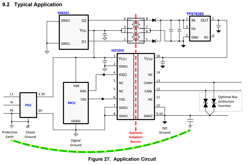
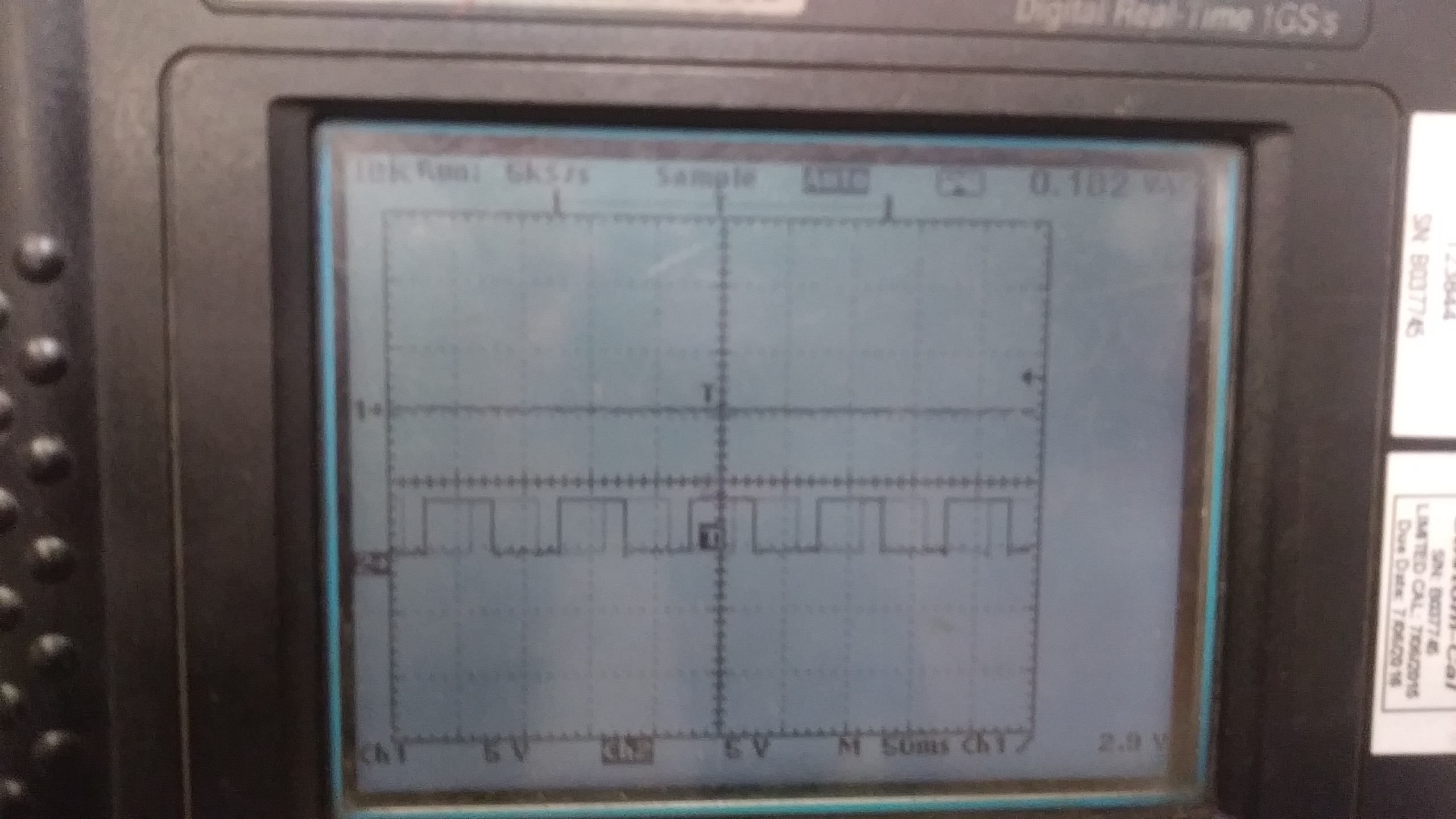
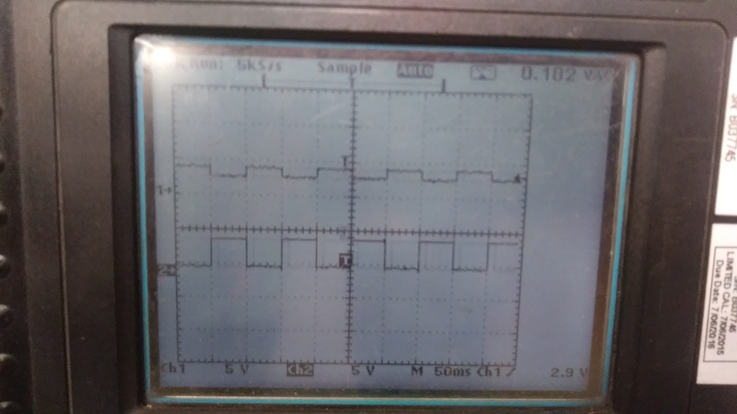
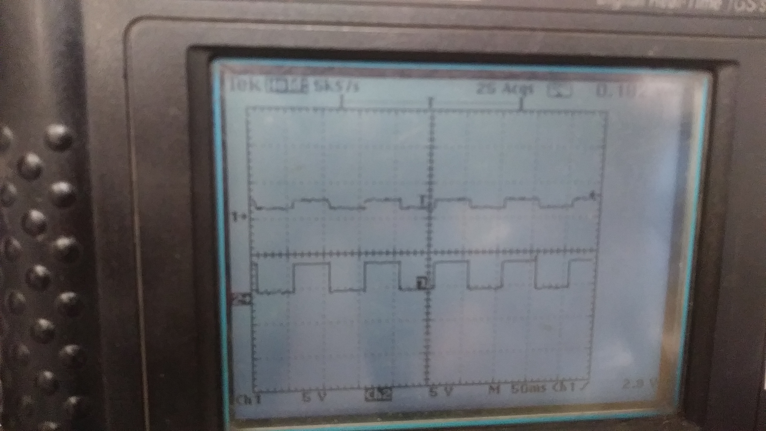
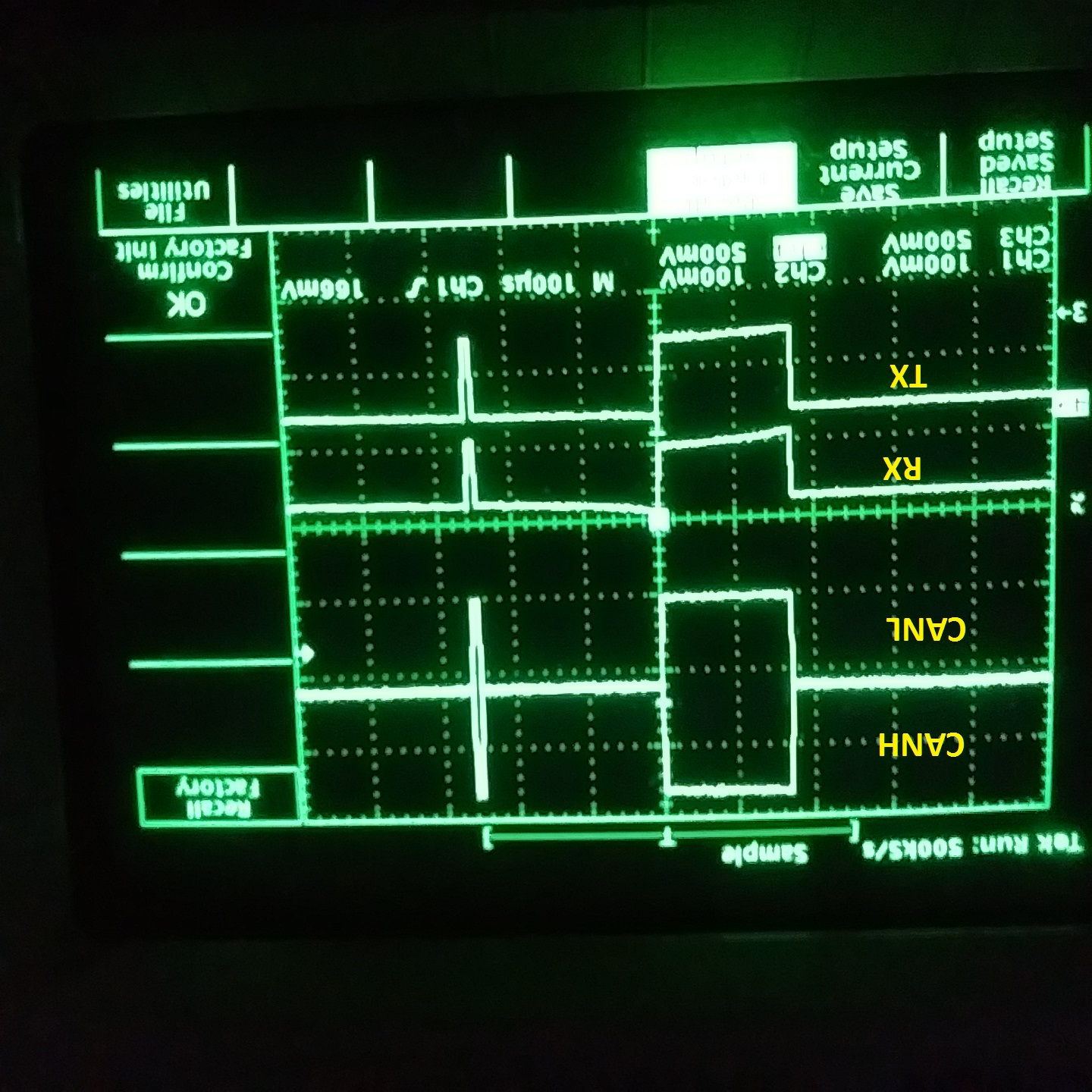
I created a design using the iso1050 dub can transciever. I designed exactly as shown in the datasheet. I can't get any meaningful signal out of it. Occasionally I'll get a few square waves but most of the signal is noise. It's not a board design problem because I (through great effort) replaced the iso1050 with an SN65HV transciever and everything worked fine. Any help would be appreciated.
Hi Todd,
I am sorry to hear you are having trouble with the ISO1050.
Would you be able to share your schematic and oscilloscope waveforms of what you are seeing? Perhaps there is an issue with one of the supplies as you said this does not happen when using the SN65HV transceiver. Just to make sure we are on the same page, you are referring to the SN65HVD1050 transceiver, correct?
Best regards,
Dan
Hi Dan,
I replaced the iso1050 with an SN65HVD251 and the CAN bus worked fine. I then reconnected the iso1050 and took the following screen shot:
Here is a schematic of my circuit:
I was transmitting eight bytes of data every 10ms @ 250kbps. The eight bytes were 7,2,20,18,39,200,125,150. Any help would be much appreciated.
Hi Dan,
I measured the voltage at Vcc1 / Vcc2. It is very stable at 4.9V. This is quite puzzling as the circuit is identical to others I've seen on this site.
I'm measuring temperatures of IGBTs in a high voltage application and want to isolate the temperature measurement module from the system PLC. I'm using the board to take temperature data and transmit it to a PLC over a CAN bus. The temperature board has its own isolated power supply and the only connection to the PLC is the CAN twisted pair.
Hi Todd,
Just to confirm, the voltage at Vcc1/ Vcc2 is stable 4.9V during communication like that shown in the scopeshot above?
I want to try to recreate this condition in our labs. Am I correct that you are transmitting the signal on TX and observing it on the scope on CANH / CANL?
When Vcc1 and Vcc2 are tied together it creates a direct short across the isolation boundary. There is no isolation between the CAN bus and the MCU in the schematic you provided. The galvanic isolation barrier must be present. An example of how to use an isolated CAN transceiver can be found on page 22 of the ISO1050 datasheet: Typical Application Circuit.
Best regards,
Dan
Yes, voltage is stable during communication like the screenshot above.
Yes, I am transmitting on TX and observing it on the scope connected to CANH/CANL.
The TX amplitude is 5v.
I have a PLC and a CAN analyzer tool on the bus as well as my board.
My board is on one end of the bus (with 120 ohm res), the PLC is a node in the middle and the analyzer tool is on the other end of the bus (with 120 ohm res).
Here is scope connected to TX:
Here is Scope connected to CANH/CANL while disconnected from bus and 120 ohm resistor connected:
Scope connected to CANH/CANL while all nodes on bus and 120 ohm resistor connected:
Scope connected to CANH/CANL with PLC powered down 120 ohm resistor connected:
Powering down the PLC cleans up the signal, but it still looks like there is no meaningful data being transmitted. My CAN tool is still not receiving my message. It always has a status of "BUS HEAVY". When I use the SN65HVD251 I have no problems communicating.
Thinking I might have a defective xciever, I changed it but to no avail. Could both of them be bad? I have three others to try.
Hi Todd,
Thank you - I very much appreciate the detailed debug with scope shots. First thing to clarify here, are the first two scope shots showing behavior you would expect? For example, here is my findings from the scopeshots you attached.
Scopeshot Description | Output |
Scope connected to TX | Okay? |
Scope connected to CANH/CANL while disconnected from bus and 120 ohm resistor connected: | Okay? |
Scope connected to CANH/CANL while all nodes on bus and 120 ohm resistor connected: | Very Poor |
Scope connected to CANH/CANL with PLC powered down 120 ohm resistor connected | Poor |
One hypothesis is that the loop delay is having an impact on this system working. The max total loop delay is longer for the ISO1050 than that of the SN65HVD251. This could be an issue if the microcontroller is not sampling at the right points and this could lead to incorrect communication - which could result in the CAN analyzer reading "HEAVY LOADING."
We could debug this with the following test:
This should show if the transceiver is working as we expect.
Best regards,
Dan
Hi Dan,
Sorry for the delay in replying. I took a long holiday weekend.
I have not resolved the problem yet but I've taken a couple of screenshots that might help.
These are the same CAN message as my previous screenshots, but I've reduced the rate to 100kbps.
This is the signal I have while using the SN65HVD251. It looks good and communicates with my CAN tool.
This is the same CAN message and same bit rate (100kbps) using the ISO1050.
Hi Todd,
No worries about the delay.
Could you monitor TX, RX, CANH and CANL with the scope? I don't have the same CAN tool available in my lab, but being that this is a transceiver, I think we should investigate these 4 signals related to the transceiver. RX should follow CANH / CANL. CANH / CANL should follow TX.
Best regards,
Dan
Hello Dan,
Thanks for taking the time to help me figure this out.
Okay, I've taken some scope shots with a 10kHz 50% duty cycle signal applied to TX. I only have a 2 channel scope at the moment but can obtain a 4 channel if necessary.
This is a shot of the PWM signal applied to TX.
Here is TX and CANH
And here is TX and CANL
Hi Dan,
I've tried a number of different sampling points, but to no avail. Wouldn't sampling points cause issues with receiving messages exclusively? All I'm trying to do is send data on the CAN bus.
Hi Todd,
Yes, sampling points should really only affect how the micro controller receives the messages from the transceiver. That is, unless you're CAN analyzer tool is expecting a certain response.
To recap we've verified:
The only thing I can think of to still check on the ISO1050 is to verify that RX is healthy. Could you capture scope shots similar to the experiment you did to verify TX to CANH / CANL is healthy for RX? You could do either CANH / CANL and RX or TX and RX (I know you only have two scope probes available with this particular scope).
If this attempt does not work perhaps we could set up a quick call to discuss this issue. I've sent you an E2E friend request so we can exchange contact information in private messages (rather than posting them on the public forum).
Best regards,
Dan
Hi Todd,
I'm going to close this thread for now. Please feel free to open a new thread if this issue is still not resolved.
Best regards,
Dan
Setting up a call would be a good idea. I've been able to obtain a four channel scope. I took some screen shots this morning.
ISO1050 @ 100kpbs (don't know why image is inverted).
SN65HVD251 @ 100kbps
Sorry about the inverted images. They imported that way. I even inverted my source and it still imported upside down here.
After looking at all four channels and comparing a good signal to bad, it looks to me like my TX and RX signals are being distorted by the ISO1050. What do you think?