This thread has been locked.

If you have a related question, please click the "Ask a related question" button in the top right corner. The newly created question will be automatically linked to this question.

DP83640: Question about Application notes from customer

Part Number: DP83640
Other Parts Discussed in Thread: DP83630

Hi Team,

My customer is looking for PHY support IEEE1588, we penetrated DP83640. I got a question want to check with expert about the application note AN-1728:

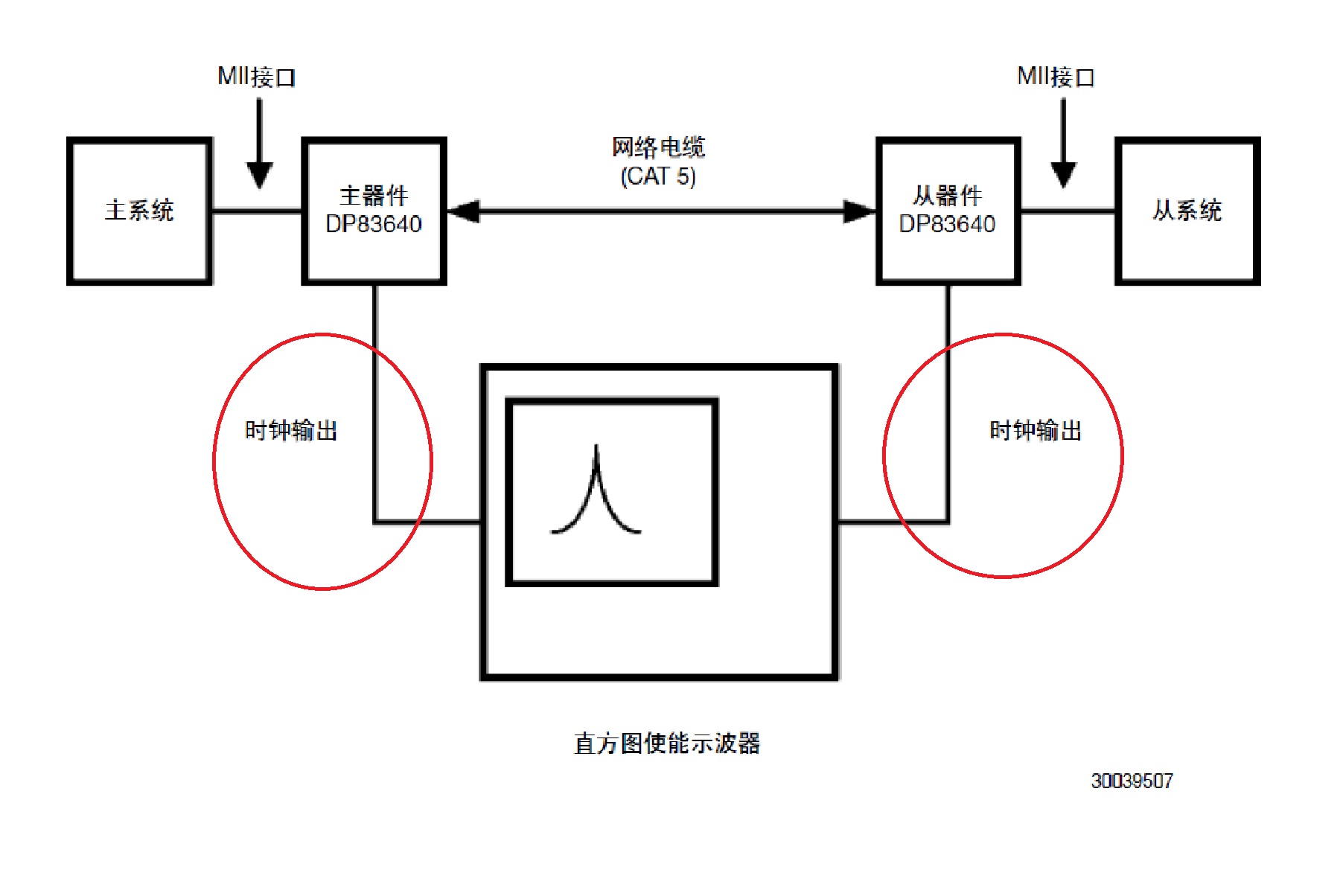
Question is that what is the red circle I highlighted in the picture mean? Is it is CLK_OUT of the two DP83640 showed in the picture?

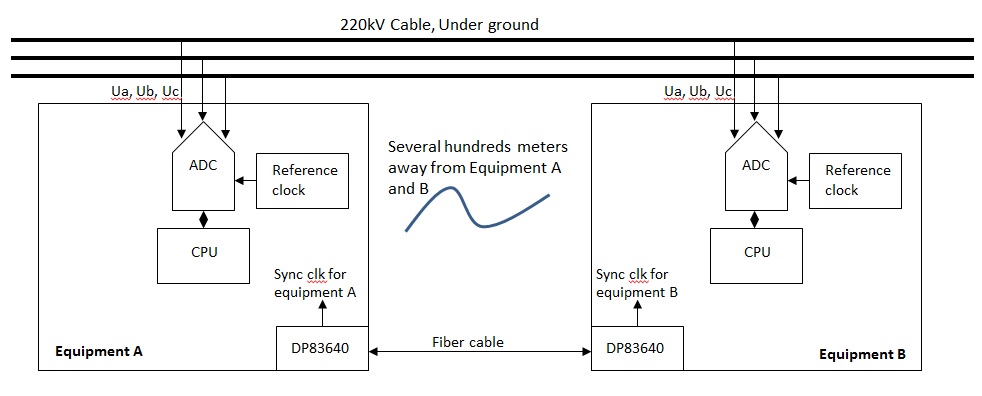
If customer use DP83640 in two different equipment which are far way from each other(May up to several kilometers), so how to sync the clock or sync the clock?

Another question is in order to sync the two equipment less than 10ns, any guidelines for customer to refer?

Thanks for the support?

Best regards,

Sulyn

  • Hi Sulyn,

    The red circled signal is a pps or "pulse per second". This can be routed to a number of the GPIO pins of DP83630 or the CLKOUT pin.

    If the distance between the two nodes is several kilometers, it seems like there will be multiple nodes between the two devices. Figuring out that system architecture is far beyond what we can do here at the PHY level.

    Achieving synchronization less than 10ns is described in this app note: www.ti.com/.../snla100

    Best Regards,
  • Hi Rob,

    Thanks for the support. Below are more detailed about this application:

    The cable which will be monitored are routed underground in city, the cable partial discharge equipment will be put separately along the cable, usually hundreds of meters away from each other(Below gives and example for equipment A and equipment B).

    The most critical now customer care is how to realize time sync or sync sampling between equipment A and equipment B.

    Time sync requirement for equipment A and B, which were put several kilometers away:  Equipment A and B need to sync the sampling and the sampling time difference should be <=10ns.


    I think TI DP83640/30 should be a choice here to realize this sync sampling, but don’t know how to realize this requirement step by step, can you give me some idea for this?


    Best regards,

    Sulyn

  • Hi Sulyn,

    This is a very large topic with a lot of important decisions that should be made. It is difficult to give you a step by step solution.

    The best thing to do is find some material on IEEE 1588, and what is supported by the CPU shown in your diagram.

    You can select an IEEE 1588 software stack that is prebuilt, or build one on your own. If you choose to build one on your own, please see the design guide: www.ti.com/.../snlu049

    If you are running Linux, I would suggest looking at the Linux PTP project. linuxptp.sourceforge.net/

    Best Regards,
  • Hi Rob and team,

    Thanks for your support. As My customer will kick off the project by end of Oct, so they are looking at if DP83640 can meet their requirement and how to. Would you pls help check below questions:

    1. Customer hope all the euipments's time are Synced and accuracy less than 10ns or a little bit higher, total equipment about 20 sets for 1 group, not sure if they can use the daisy-chain connect like showed below;

    2. If customer can use the diasy-chain connect, then When the PHY for link-up(PHY slave) received the IEEE1588 network message, does it need to send to the PHY for link-down on the same equipment? Or it just need send to FPGA, then FPGA send the system clock by using the 25MHz from PHY for link-up and the PHY for link-won will automatically extract the       network clock, then send the IEEE1588 network message to another equipment's Link-up PHY with same clock phase?

    3. If customer can't use the daisy-chain connection, is these something we understand wrong with page 6 showed in our AN?

    snla100a.pdf

    Below are the simplified block diagram for showing this case:

    If this doesn't work to meet customer requirement, any solution to help realize the requirements for customer? Thanks.

    We need your great support to look into this important biz for us, thanks.

    Best reagards,

    Sulyn

  • Hi Team,

    Any expert can help me on above important question from customer? Customer can use either MII or RMII interface.

    Thanks.

    Best regards,

    Sulyn

  • Hi Sulyn,

    1. Yes, they could use the daisy chain shown below. The slave port of the DP836x0 could provide the SyncE reference clock to the other PHYs which will improve accuracy.
    1.a The clock cannot be fanned out to 3 devices in parallel as shown in the diagram. The customer should use a low jitter buffer to distribute the clock if an FPGA, ADC, and downstream PHY needs it.

    2. It depends on the clock type being used. The PTP message will have to be handled by the FPGA in some way. The FPGA will have to extract the network clock. If this is a boundary clock, as defined in IEEE 1588, then the downstream PHY will act as a master clock and send out PTP messages accordingly. If this is an ordinary clock, the PTP messages will be forwarded directly. The behavior of the FPGA should be determined by what type of clock the customer chooses to implement.

    RMII can be used. It may be easier to use MII because the 25MHz clock domain will be consistent.

    Best Regards,