This thread has been locked.

If you have a related question, please click the "Ask a related question" button in the top right corner. The newly created question will be automatically linked to this question.

THS8200-EP: Hsync out and/or Vsync out does not locked to input signal after power recycle or input format change

Part Number: THS8200-EP
Other Parts Discussed in Thread: LMH0031, , THS8200, TVP7002

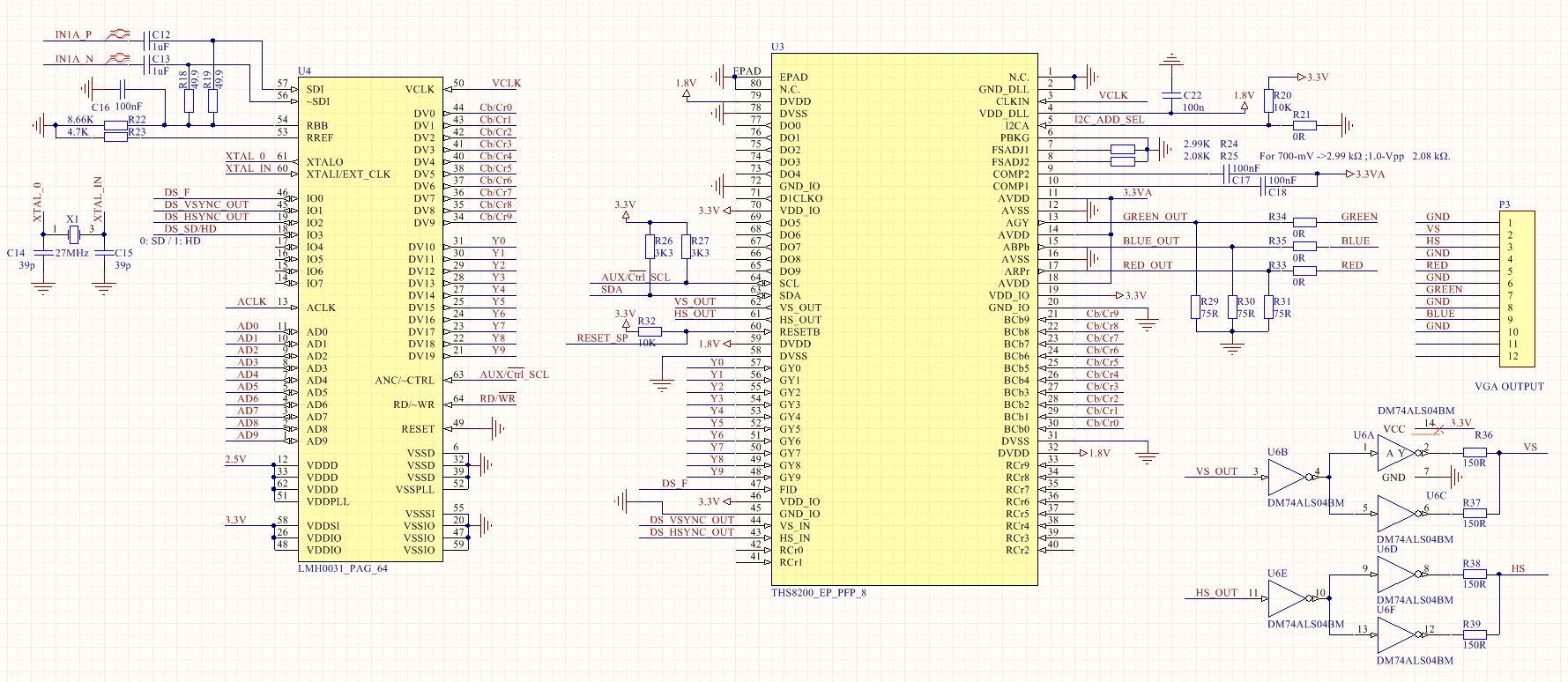
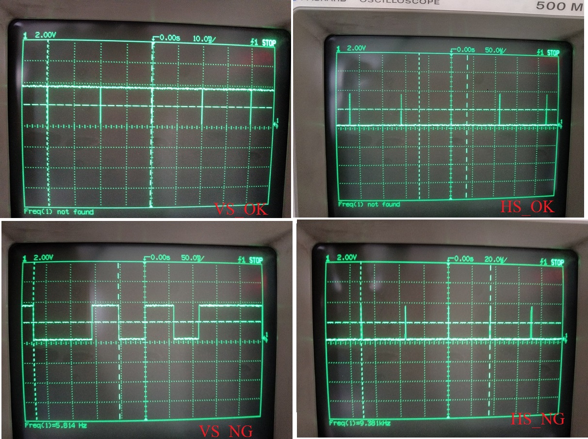
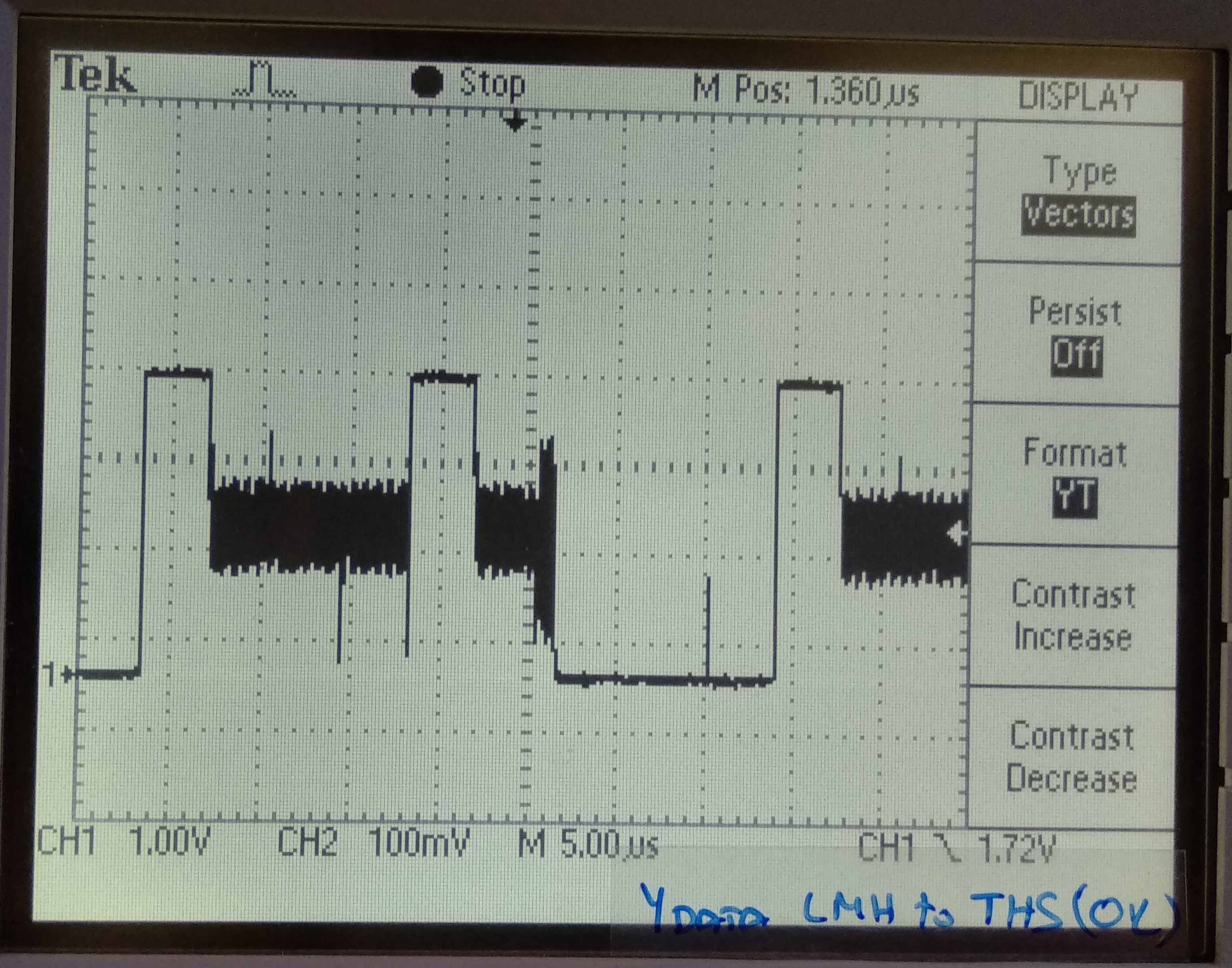
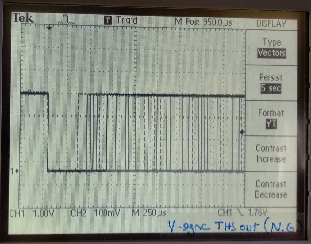
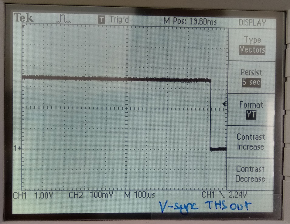
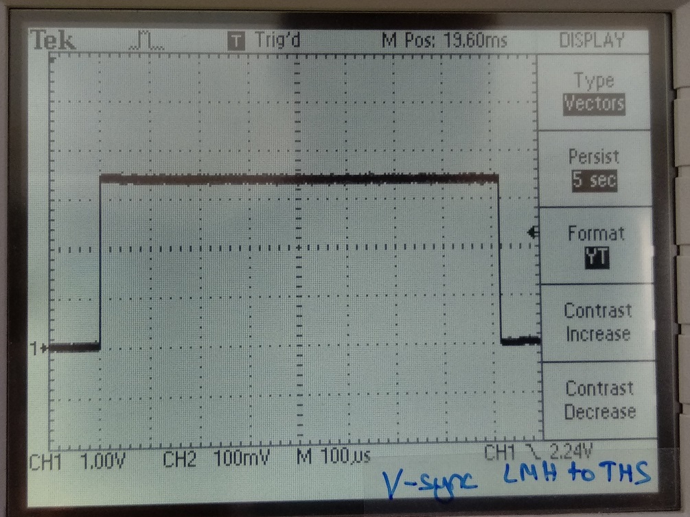
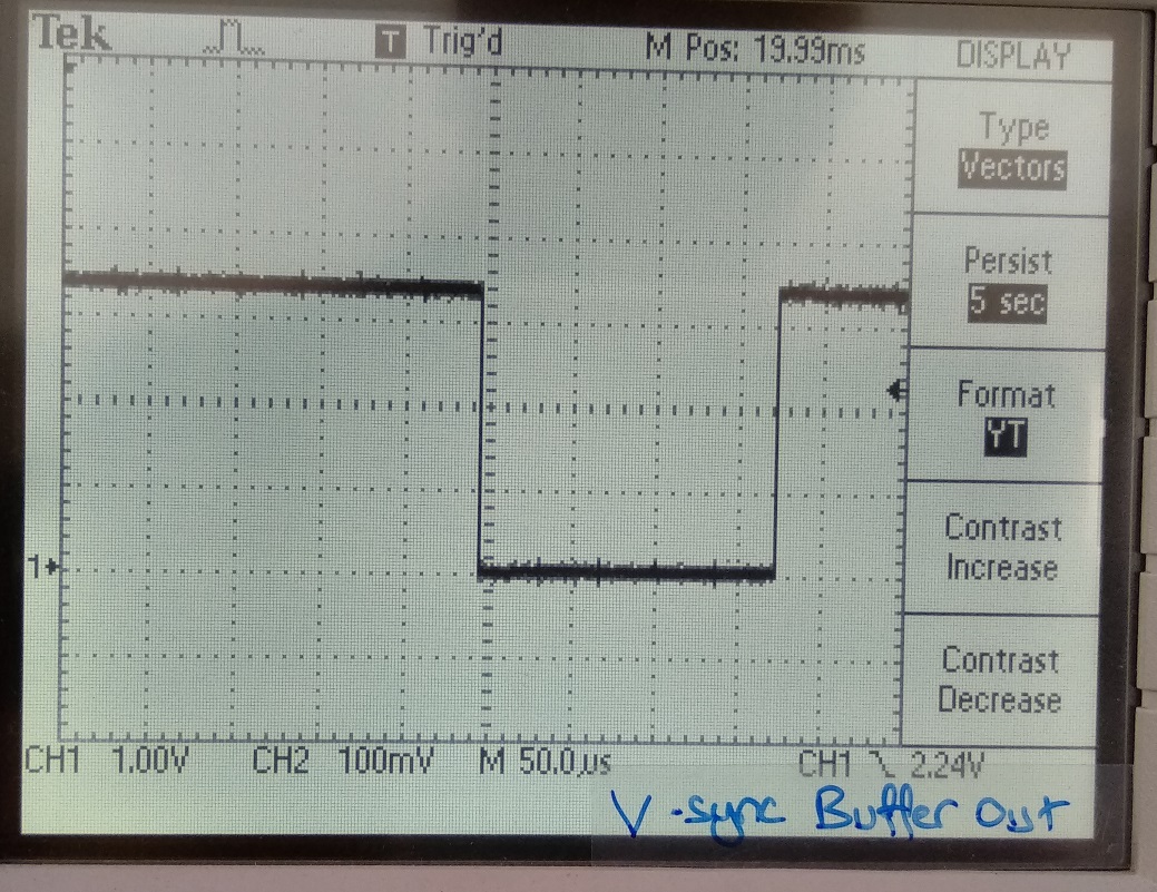
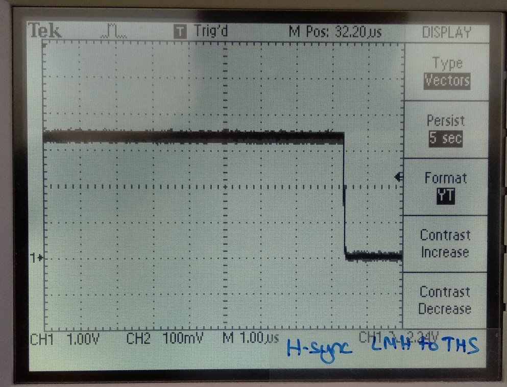
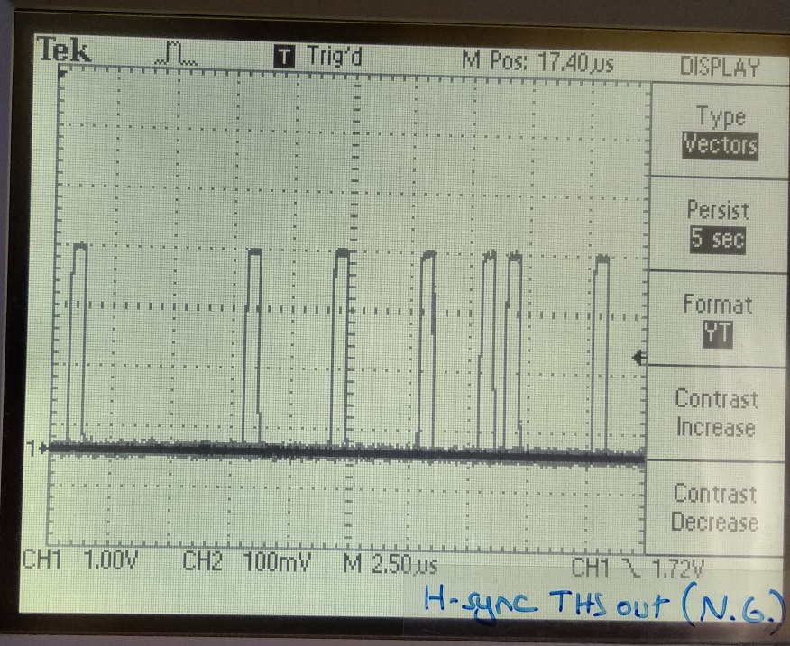
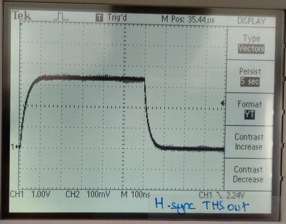
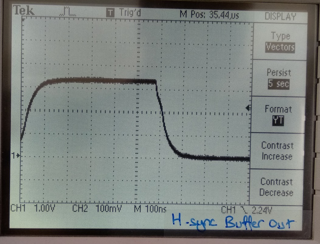
I working on a HDSDI to VGA converter project. VGA monitor does not sense the input format due to irregular Hsync or Vsync pulses. RBG ADC ouputs are Ok. Hsync out and/or Vsync out  does not locked to input signal always. Problem occurs randomly, when it is locked it keeps running correctly untll input signal change or power on-off.The source to THS8200-EP is  LMH0031 . 20bit Video data , HS,VS , F are connected to THS8200-EP. Both setting DS and ES has same results. HS and VS from LMH0031 is ok always.

  • Alaattin,
    Unfortunately this is not very much information to work with.
    Does this affect multiple boards/devices?
    Can you provide schematic?

    Regards,
    Wade
  • Hi Wade,

    I have 2 test board. Both have the same problem. Please see the attached schematic.

    We will design a new PCB for some changes, if this issue is related the wrong design I want to solve it too.

    Regards,

    Alaattin

  • Alaattin,
    I apologize for delay in getting to review your schematic.
    I do not see any major issues with schematic.

    When you indicate that if works correctly when HS VS are locked. How are you determining they are locked?

    I notice that you have double buffered the VS_OUT and HS_OUT. I am not certain if this delay is significant relative to the data.
    Can you give better description of differences between working and non-working cases?

    Regards,
    Wade
  • Wade,

    Below I send the scope photos of HS_OUT and HS_OUT for both case.. In non-working case, VS_OUT and HS_OUT are random pulses, they are not periodic.

    HS_OK

    VS_OK

    HS_NG

    VS_NG

    Best regards,

    Alaattin

  • Thanks Alaattin.
    Unfortunately, the images did not seem to come through. Could you try to repost? Use the "insert code, attach Files and more..." dialog.
    After discussing with another person with some experience on this device, he suggested the following:

    Measure the H-sync at various points along the path from LMH output to THS output, middle of buffers, buffer outputs, connector output, and if possible at the monitor input and generate eye diagrams.
    You can get an eye diagram by triggering on falling edge, turning on persistence on the scope and then use holdoff or delay to zoom in on the next falling edge. There may be significant jitter on the Hsync (or possibly Vsync) lines. Perform same examination of Vsync.

    It is suspected that the SDI input may have too much jitter. Looking at eye diagrams along the path will help determine this.

    Regards,
    Wade
  • Alaattin,
    I am not sure exactly where you probed for the above waveforms.
    However, we really need to see the sync signals going into the THS8200 from the SDI RX and also the syncs coming out of the THS. I suspect that is what you have shown.
    Can you indicate what video format is being transmitted for these captures?
    Additionally, we need to see what the eye diagram looks like coming out of the SDI RX output, and through the chain of devices to see where the issue starting.

    Regards,
    Wade
  • Hi Wade,

    The waveform I sent were the outputs of the Buffer. THS output.  Before the buffer waveforms are allmost same.

    Please check the following new waveforms you requested. Measurement points are noted on the waveforms. N.G. is when not working..  Waveforms at measurement points from LMH to THS signal are same in both working and non-working cases

    Video Format is 1080 50i.

    I notesed that Y0 -Y9 have an clock noise, but Cr0-Cr9 are clean but they are same for both cases.

    Best regards,

    Alaattin

  • Thanks for the additional data.
    My first impressions are that something is not right with the LMH0031.
    I would recommend posting a new E2E thread with that device as the reference part. It should get routed to the teams that support it.

    Aside from that, I can provide some comments on possible debugging.

    The clock from the LMH is pretty sinusoidal, and from the plot "appears" to be ac coupled. Also, most of your zoomed in shots show very slow rise/fall times. Does your scope probe have very large capacitance or possibly poor probe grounding?
    Or possibly the traces are long on the board from LMH to THS. though, the rise/falls seem large after the buffers as well.
    If it is the probe, can you find lower capacitance probe/improve grounding?

    There is definitely an issue with the data from the LHM with respect to the "noise" seen around 2V. Uncertain what would cause this, as it is a digital output. Possibly you have data lines shorted together? When they are in contention it shows up around 2V. Can you zoom in on a region that shows where it enters this ~2v noisy region? Do all the DV outputs for Y0-Y9 have same noise, and none for the Cr?

    Is the LMH showing lock?

    It may also be helpful to capture Vsync and hsync from LHM to THS with VCLK on same screen to see relationship triggering on each falling edge of the syncs. Zooming in to see the edge rate relative to clock edge rate.

    Hopefully this helps make some additional progress.
    Regards,
    Wade
  • Hi Wade,

    I encounter the problem when both DS and ES input from LMH to THS. As I understand from the THS datasheet  that if DS is set, THS creates sync outputs from the incomming DS regardless of the Video data.
    Vsync and Hsync from LMH to THS are same in both working and not working case, but the Sync outputs from THS are abnormal in non-working case. So I thought that this could be locking problem of THS to input signals. Working and non-working condition switch  with the power up, or input signal on off. While started as working,  it does not stop working. 

    I suspected for wrong  Vclk phase from LMH to THS , so THS could not lock to it. But I have not seen any register to modify the Vclk phase.

    In both case LMH locks. All Y0-Y9 has the noise (possibly Vclk interference ), CrCb 0-9 does not have same noise. This noise seen on both cases, so does not effect the output.

    I am not sure about  the probe capacitance/quality. I try to find out another one.

    Best regards,

    Alaattin

  • Alaattin,
    I agree that the THS should be generating valid syncs. However, the data input appears to be grossely incorrect. These are digital inputs, and the output of the LMH appears to be sitting at mid rail for long duration. This could be indicative of a short. With this type of issue, the LMH outputs are all in question and debugging of the LMH issues should occur prior to the THS debugging.

    Regards,
    Wade
  • Can you get some zoomed in scope shots of the "noise" on the digital outputs? This may help provide a clue to the cause.
    I also suggest posting on the issues with the LMH in separate E2E post. You can post the link here for reference as well.
    I did note some comments in other E2E post on resets, and usage of crystal oscillator with the LMH.

    Regards,
    Wade
  • Hi Wade,

    I found a solution for the issue. I connected 1K resistor between Vclk and GND close to THS. I tested the circuit many times for more than 3 days, I have not encountered the problem again.

    Best Regards

    Alaattin

  • Great, glad you found a solution.
    Curious, when you probe it after the 1k pull down, does vclk look more like a cmos clock and not sinusoidal?

    Regards,
    Wade
  • Hi Wade,

    Vclk scope waveforn after 1K pulldown as follows.

    Thanks you for your help.

    Regards,

    Alaattin

  • Hi Wade,

    I found  register settings for VGA output formats for the following output formats using the excell sheets supplied. (tvp7002_THS8200_VGA_YPbPr_settings.xls). Now we need component (YPbPr) output format for the same resolution. Finding out the correct register setting values from the datasheet will take long time, the board will be used soon. Can you supply register setting list for the format? 

    * 1920x1080 50i ( 20bit input )

    *1920x1080 60i ( 20bit input )

    * 1920x1080 25p ( 20bit input )

    *1920x1080 30p ( 20bit input )

    *720 60p ( 20bit input )

    Regards

    Alaattin

  • Alaattin,
    Unfortunately, I do not have a way to generate this data readily.
    Regards,
    Wade