Other Parts Discussed in Thread: DSI-TUNER

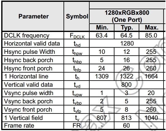
picture 1
The picture 1 is the Lvds panel SPC.


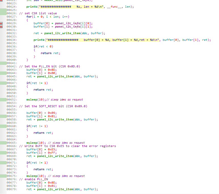
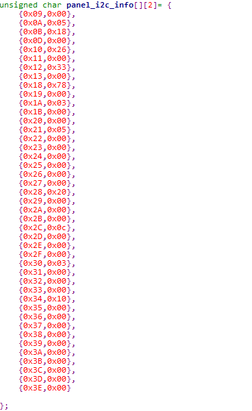
picture 2
The picture2 is CSR setting.
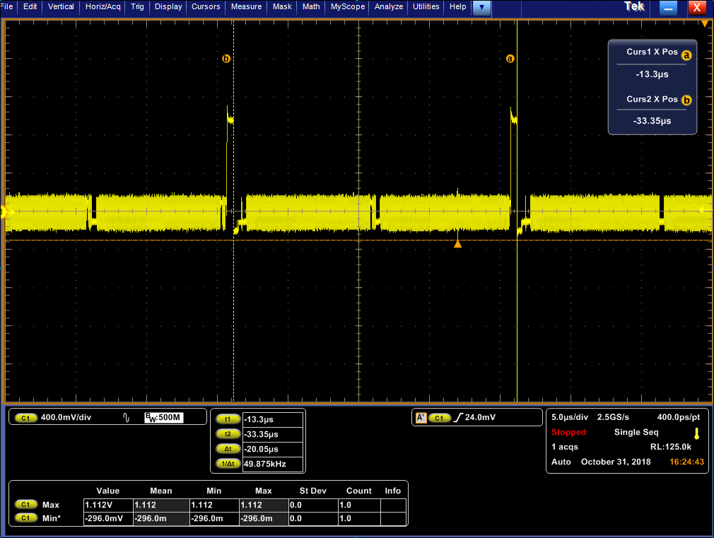
TEST result:
1、MIPI CLK

2、MIPI_DATA
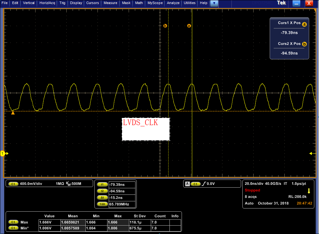
3、LVDS OUT :CLK
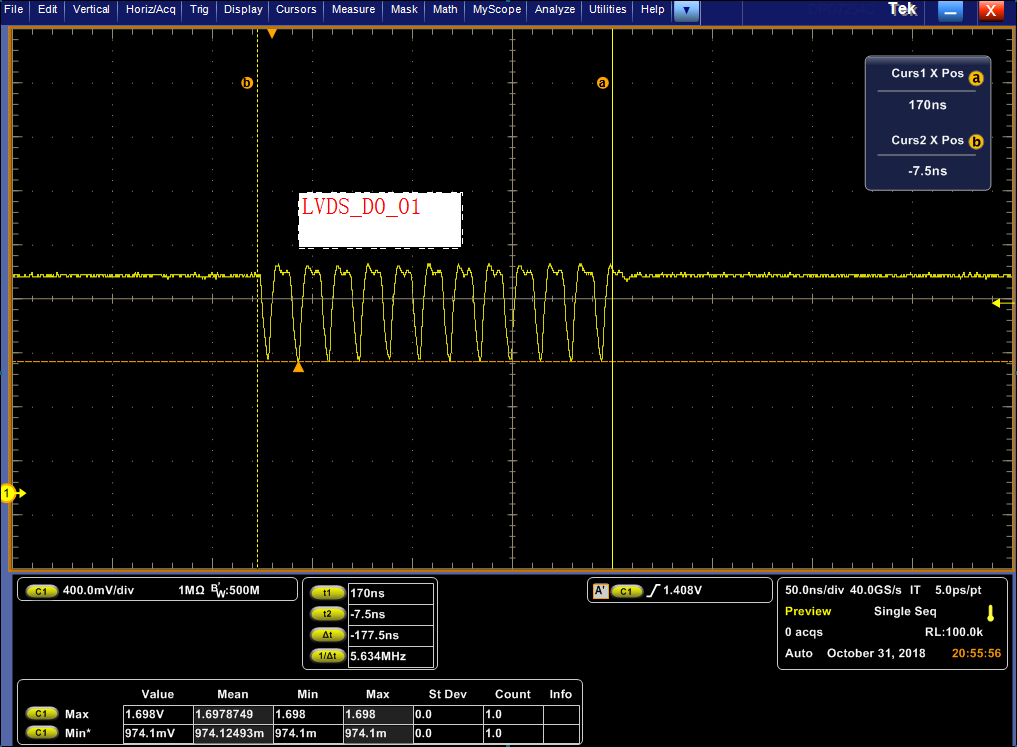
4、LVDS OUT:D0

LVDS OUT: D1/D3

LVDS OUT :D2

USE tuner tool test pattern :
LVDS OUT:CLK
LVDS_D0
LVDS_D1

LVDS_D2

LVDS_D3

Circuit diagram:

Question:
1、The tuner tool setting is OK?
2、LVDS out is NG,why,help me。What can I check?
3、IN Test pattern mode,the LVDS is OK?
4、Can you provide me with a usable setting according to my LCD specification.