This thread has been locked.

If you have a related question, please click the "Ask a related question" button in the top right corner. The newly created question will be automatically linked to this question.

TCAN4550-Q1: Transmission with incorrect length.

Part Number: TCAN4550-Q1
Other Parts Discussed in Thread: TCAN4550

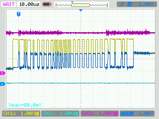
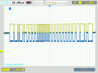
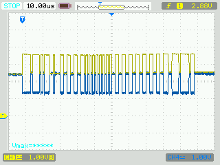
I’m setting up two TCAN4550 modules to send messages back and forth but I’m having a problem with the Transmit operation.  I'm trying to send a Standard ID CAN message with 32bytes of data.  I was expecting to see a single transmission with a length of ~290us but what I’m seeing is a repeated 67us length transmission.  This transmission gets repeated every 91.6us.  I've attached a Word document that shows my setup along with some oscilloscope captures that show the transmissions.


Thanks,


Joe


TCAN_TransmitProblem.docx


  • Joe,

    I'll look over the code, the CAN bus signals look good from a signal integrity standpoint, so I don't think that's causing any issue. The repeated attempts at transmission seem to point to the device recognizing an error in the frame, and re-trying.

    • Can you read the TEC and REC values in register 'h1040 while this is happening? I want to see if the error counters are incrementing.
    • In the abbreviated message, is the data that is being sent match up with what you expect until it gets cut off?
    • How is the device on your board being configured? I assume the code is for the transmit device.

    Let me know if you can get this information, and I'll reply when I get some more information from the code.

    Regards,

  • Hi Eric,

    1.) I setup my code where it would transmit 3 times then Cancel the transmission Request. I then added a ~1 second delay before looping back around to transmit 3 more times. After each attempt, I read the Error Counter register and saved it off to a variable. I set a breakpoint just before the 1 second delay.

    The TEC variable in the Error Counter was set to 0x80 and never incremented. The REC remained at 0x00.

    2.) The data being transmitted sort of looks like the data I was expecting. I maybe off or have my Endianness wrong but what I was programming was
    Header #1: 0x0014 0000 (@0x8100)
    Header #2: 0x0185 0000
    Payload: 0xCCCCAAAA, 0xCCCCAAAA, 0xCCCCAAAA -->

    What I captured on the scope was: (Reading the graph from left to right)
    1st Byte: 0x04
    2nd : 0x28
    3rd : 0x5A
    4th : 0xAA
    5th : 0xAA
    6th : 0xCC
    7th : 0xCC
    (It looks like a total of ~ 75 bits are being transmitted before the sequence starts over)

    3.) The 2nd device that's pictured (Green Board) uses exactly the same setup as the TCAN-EVAL Board but the transmitter is not enabled. It simply stays in Normal Mode and does nothing.

    Let me know if you need my register settings.

    Thanks,
    Joe
  • Joe,

    Thanks for all the information and the verification of the error state. That's good news at least. It looks like the data you're transmitting is being interpreted correctly. Go ahead and send the register settings so I can verify the FIFO and buffer settings, as well as any interrupts that might be getting thrown.

    Regards,

  • Hi Eric,

    I haven't gotten to the point where I'm validating the Interrupts.  If you need me to look at anything specific, let me know.

    The code snippet below is the Initialization of the TCAN4550 that I'm using.  Once the device is initialized, I enter into that Transmit routine where I'm sending that "dummy" packet.  The CAN_Trans_Init() routine that I included below is slightly different than the CAN_Trans_Init() in the first entry of this thread.  I added an initialization of the TXBuffer.

    After each line of code, I embedded the register values.  The format of the register values is:

    Command,Address,# of doublewords

    Data

    void CAN_Trans_Init(uint32_t dwCommPort)

    {

       volatile uint32_t i;

       volatile uint32_t dwError = 0;


       //-- RESET the chip (This pulls the RST pin High for 12us and then returns Low)

       CAN_RESET();  


       //--Test the CAN Transceiver

       CAN_Trans_Commands(CAN_PORT, CAN_DEVICE_ID);

         /*-- Run a test to ensure

           * device compatibility and communication

             CAN_DEVICE_ID = 0x41000008

           */


       if(!dwError)

           {

       //-- Setup the Transceiver for Initialization --

           CAN_Write(dwCommPort,&TCAN4550_W_CCCR_INIT_ENABLE[0]); // 0x1018

                                         //Control Register Write to being

                                         //the initialization process and make registers

         TCAN4550_W_CCCR_INIT_ENABLE[]=

    {

         0x61101801, (Command,Address,# of double words)

         0x00000003, (Data)

    }


                                         //write accessible.


           CAN_Write(dwCommPort,&TCAN4550_W_STANBY_NOTCONFIG[0]); // 0x0800

                                                   //Standby Mode, Pin Config

                                                   //& MCAN_CONFIG = 0

    TCAN4550_W_STANBY_CONFIG[] =

    {

         0x61080001,

         0x08440462,

    };


       //-- Setup the Interrupts --

       // GPIO1 - New Message Received FIFO0 or 1

       // GPO2 - TX Complete

       // nINT - CAN Bus Flags

           CAN_Write(dwCommPort,&TCAN4550_W_nINT_CLEAR[0]);                 // 0x0820

                                                     //Clear Interrupt/Diagnostic Flags

    TCAN4550_W_nINT_CLEAR[] =

    {

         0x61082001,

         0x00000000,

    };


           CAN_Write(dwCommPort,&TCAN4550_W_nINT_INTERRUPT_ENABLE[0]);       // 0x0830

                                                     //Enable interrupts for nINT

    TCAN4550_W_nINT_INTERRUPT_ENABLE[] =

    {

         0x61083001,

         0x6F680000,

    };


           CAN_Write(dwCommPort,&TCAN4550_W_INTERRUPT_REGISTER_SETTINGS[0]); // 0x1054

                                                     //Program the Interrupt Register

    TCAN4550_W_INTERRUPT_REGISTER_SETTINGS[] =

    {

         0x61105401,

         0x00000211,

    };

           CAN_Write(dwCommPort,&TCAN4550_W_ILS_AND_ILE[0]);     // 0x1058 & 0x105C

                                                     //Assign Interrupts to M_CAN_INT1

                                                     //Enable EINT0 & EINT1

    TCAN4550_W_ILS_AND_ILE[] =

    {

         0x61105802,

         0x00000011,

         0x00000003,

    };


       //-- Setup the BIT Timing --

           CAN_Write(dwCommPort,&TCAN4550_W_NOMINALBIT_TIMING_REG[0]); //0x101C

                                                     // 40MHz/4, Bit Sample settings

                                                    // Bit Time = 1.111MHz

    TCAN4550_W_NOMINALBIT_TIMING_REG[] =

    {

         0x61101C01,

         0x02030501,

    };

           //-- Setup the TXBuffer & FIFOs --

           CAN_Write(dwCommPort,&TCAN4550_W_TXBUFFER_CONFIG[0]);       // 0x10C0

                                                     // 5 Transmit FIFO/Queue Buffers

                                                     // Start Add = 0x8100

    TCAN4550_W_TXBUFFER_CONFIG[] =

       {

         0x6110C001,

         0x05000100,

       };


           CAN_Write(dwCommPort,&TCAN4550_W_TXEVENTFIFO_CONFIG[0]);   // 0x10F0

                                                             // 3 Transmit FIFOs

                                                             // Start Add = 0x81E0

    TCAN4550_W_TXEVENTFIFO_CONFIG[] =

       {

           0x00000001,

           0x6110F001,

           0x020301E0,

       };


           CAN_Write(dwCommPort,&TCAN4550_W_TXELEMENTSIZE_CONFIG[0]); // 0x10C8

                                                               // DLC = 32 Bytes

    TCAN4550_W_TXELEMENTSIZE_CONFIG[] =

       {

           0x6110C801,

           0x00000005,

       };


           //-- Setup the RX Buffers and FIFOS

           // RX_FIFO0 - Used for the 64 byte messages.

           // RX_FIFO1 - Used for the 8 byte commands.

           CAN_Write(dwCommPort,&TCAN4550_W_RXFIFO0_CONFIG[0]);       // 0x10A0

                                                           // 4 RX FIFO 0 Buffers

                                                          // Start Add = 0x8200

    TCAN4550_W_RXFIFO0_CONFIG[] =

       {

         0x6110A001,

         0x28040200,

       };

           CAN_Write(dwCommPort,&TCAN4550_W_RXFIFO1_CONFIG[0]);       // 0x10B0

                                                           // 4 RX FIFO 1 Buffers

                                                          // Start Add = 0x8340

    TCAN4550_W_RXFIFO1_CONFIG[] =

       {

         0x6110B001,

           0x04040340,

       };


           CAN_Write(dwCommPort,&TCAN4550_W_RXELEMENTSIZE_CONFIG[0]); // 0x10BC

                                                           // RX FIFO & BUFFER Elements

    TCAN4550_W_RXELEMENTSIZE_CONFIG[] =

       {

         0x6110BC01,

         0x000010BC,

       };


           //-- Setup the SID Filters --

           CAN_Write(dwCommPort,&TCAN4550_W_SID_FILTER[0]);           // 0x1084

                                                           // SID FILTERS

    TCAN4550_W_SID_FILTER[] =

    {

         0x61108401,

         0x00040000,

    };


           CAN_Write(dwCommPort,&SID_FILTER_IDS[0]);                   // 0x8000

                                                          // SID IDS

    SID_FILTER_IDS[] =

    {

         0x61800004,

         0x30000000,

         0x30010001,

         0x30030003,

         0x28100010,

    };


           //-- Dummy Write into TXBuffer0 to correct the BEU setting.

           CAN_Write(dwCommPort,&TCAN_W_TXBUFFER0_DUMMY[0]);

    TCAN_W_TXBUFFER0_DUMMY[] =

    {

       0x6181000A,

       0x12345678,

       0x9ABCDEF0,

       0x12345678,

       0x9ABCDEF0,

       0x12345678,

       0x9ABCDEF0,

       0x12345678,

       0x9ABCDEF0,

       0x12345678,

       0x9ABCDEF0,

    };


           //-- Put the Chip into Normal Mode

           CAN_Write(dwCommPort,&TCAN4550_W_CCCR_NORMALMODE[0]);       // 0x1018

                                                         // Control Register

                                                         // Clear the CCE and INT bits


    TCAN4550_W_CCCR_NORMALMODE[] =

    {

         0x61101801,

         0x00000100,

    };


           CAN_Write(dwCommPort,&TCAN4550_W_NORMAL[0]);     // 0x0800

                                                       // Mode of Operation - Normal

    TCAN4550_W_NORMAL[] =

    {

         0x61080001,

         0x084404A2,

    };

           }

    }

    Thanks for the help,


    Joe

  • Joe,

    Thank you for this, it helps tremendously. One thing that confused me is you have two messages going to register 1058, which is an interrupt mapping configuration register. Is this intentional?

    It looks as though one byte of your intended data payload is getting through and then the message abruptly stops. Then the controller continuously tries to re-transmit until it sends the message correctly, which never happens in your case.

    The TEC variable being set to 0x80 means that that bit field was 1000 0000, which would indicate the Error Counter is at 128, and this was set only after 3 transmits? When the event counter >127, the device goes into error-passive mode. But if it's not incrementing after that and the transmission repeat is still happening, then that doesn't explain the issue.

    Can you probe RXD and GPO2 while the transmission repeats are happening? And have you ever let them go to see how long before the controller stops?

    Regards,
  • Hi Eric,


    Sorry, I was out the last few days. You made the comment:


    One thing that confused me is you have two messages going to register 1058, which is an interrupt mapping configuration register. Is this intentional?


    [JEC]

    I’m assuming you were looking at the following code snippet. I have CAN_Write() setup such that it can write to registers that are sequential.  In other words.  0x00000011 is being written to Address 0x1058 and 0x00000003 is being written to Address 0x105C.


      CAN_Write(dwCommPort,&TCAN4550_W_ILS_AND_ILE[0]);     // 0x1058 & 0x105C

                                         //Assign Interrupts to M_CAN_INT1

                                        //Enable EINT0 & EINT1

    TCAN4550_W_ILS_AND_ILE[] =

    {

         0x61105802,

         0x00000011,

         0x00000003,

    };


    It looks as though one byte of your intended data payload is getting through and then the message abruptly stops. Then the controller continuously tries to re-transmit until it sends the message correctly, which never happens in your case.


    [JEC] It looks like 6 bytes of data are being sent. And yes, this message is continuously being transmitted. The message appears to be:


    0x04   0x28   0x5A   0xAA   0xAC  0xCC   0xCA   0xA7

    When I expect to see

                             //Format Header#1 (This data is being written to Address 0x8100)

             CAN_TX_Buffer[2] = 0x00140000;

             //Format Header#2

             CAN_TX_Buffer[3] = 0x018D0000;


             //Move Message into the Local Transmit Buffer

             CAN_TX_Buffer[4] = 0xCCCCAAAA;

             CAN_TX_Buffer[5] = 0xCCCCAAAA;

             CAN_TX_Buffer[6] = 0xCCCCAAAA;

             CAN_TX_Buffer[7] = 0xCCCCAAAA;

             CAN_TX_Buffer[8] = 0xCCCCAAAA;

             CAN_TX_Buffer[9] = 0xCCCCAAAA;

             CAN_TX_Buffer[10] = 0xCCCCAAAA;

             CAN_TX_Buffer[11] = 0xCCCCAAAA;


    I changed up the message and can see that some of the data is being transmitted from the buffer. The Headers don’t seem to match.


    The TEC variable being set to 0x80 means that that bit field was 1000 0000, which would indicate the Error Counter is at 128, and this was set only after 3 transmits? When the event counter >127, the device goes into error-passive mode. But if it's not incrementing after that and the transmission repeat is still happening, then that doesn't explain the issue.


    [JEC] I reran the TEC increment test.  This time, I powered the TCANEVAL module down completely which forced the Error Count Register to 0.  If I monitor the TEC variable directly after a power cycle, I can see this it does increment from 0 up to 128 in steps. Once it reaches 128, it stops incrementing.  Periodically I can see the CEL variable in the Error Counter Register toggle between 0 and 1.   What's odd, RESETs the chip just before initialization.  I was expecting the Error Count Register to return to zero after the RESET but it remains at 128.  The only way I have been able to get the Error Counter back to zero is through a power cycle.

    I have attached a document that contains some scope screen shots.  The interesting thing that I found was the very first few transmissions look different from the other transmissions.  The length of these first transmissions is not correct but it is different.  I also made some comments in the attachment about GPO2 and GPIO1.

     4810.Scope Screen shots.pdf


    Let me know if you need anything else.

    JC

  • Joe,

    Thanks for the clarification on the writes, and I guess it's good that there are no errors being detected.

    In the first scope shot, the end of the frame looks like it has 6 dominant bits, followed by 11 recessive, which is the active error flag (6 dominant bits for the active error, 8 error delimiter bits, and 3 interframe spacing bits). In the second screenshot, there are ~24 recessive bits which resembles a passive error flag, but there 7 recessive bits too many; there should only be 17, 6 recessive for the passive error, 8 error delimiter bits, 3 interframe spacing.

    Can you turn off the DAR bit in register '1018? It is bit [6]. What might be happening is that since your other device is transmitting nothing, the device that's continuously resetting is getting no acknowledgement so it sees that as a transmission failure, but logs no error for it. Disabling the DAR bit (writing bit[6] of register 'h1018 to 1) should stop your device from continuously transmitting the same message over and over.

    Let me know if this changes anything. And thank you very much for your patience while we try to figure this out.

    Regards,

  • Hi Eric,

    I updated the code with the request you made.  See below.


    //-- Put the Chip into Normal Mode

    CAN_Write(dwCommPort,&TCAN4550_W_CCCR_NORMALMODE[0]);      // 0x1018

                                                               // Control Register

                                                               // Clear the CCE and INT bits

                 ORIGINAL CODE                   UPDATED CODE

         TCAN4550_W_CCCR_NORMALMODE[] =       TCAN4550_W_CCCR_NORMALMODE[] =

             {                                   {

              0x61101801,                         0x61101801,

              0x00000100,                         0x00008140,

             };                                    };                                                                  


    CAN_Write(dwCommPort,&TCAN4550_W_NORMAL[0]);             // 0x0800

                                                             // Mode of Operation - Normal

                        TCAN4550_W_NORMAL[] =

                         {

                          0x61080001,

                         0x084404A2,

                         };


    With the DAR bit set, my test only transmits a single message.


    I set my scope up for "Single Shot" Mode so this is the very first transmission right after the chip is initialized.  The transmission looks like the screen shot I took before.  If I keep repeating the transmission, all messages look like the scope shot below.


    Thanks,


    Joe

    P.S

    I’ve been experimenting on my own and have found 2 things that don’t seem quite right. I have taken my code and stripped out all of the register settings for the Interrupts and the Receive FIFOs so I’m left only with the configuration of the Transmit Buffer and FIFO. 


    The following registers are being programmed in this specific order.:

    0x1018         à       0x00000003                           Enable Initialization

    0x0800         à       0x08440442                           Standby/Not Configured

    0x101C       à       0x02030501                            TX Bit Timing

    0x10C0       à       0x05000100                            TX Buffer Configuration

    0x10F0         à      0x020301E0                          TX Event FIFO Configuration

    0x10C8       à       0x00000005                            TX Buffer Element Size

    0x8100         à      0x12345678                            32 byte Dummy Write to the Transmit Buffer

    0x1018         à      0x00008140                             Put in Normal Mode, No Auto TX, FD

                                                                                   Enabled,Bosch CAN FD

    0x0800       à      0x084404A2                             Normal Mode of Operation


    Item #1: I setup a READ operation after every write step to ensure the right setting are being programmed into the register.  All of the registers with the exception of register 0x1018 had the expected value.  After writing to register 0x1018, I read back the following information.


    A RESET was conducted before any Write occurred.

    Wrote:                     Read:

    0x00000003             0x0000001B

    0x00008140             0x00008159


    These values don’t seem right. All of the other registers that were written returned the correct value.


    Item #2: The RST pin doesn’t appear to operate as specified. Before the Initialization of the chip, the RST pin is pulled High for 12us and then returned Low for ~30us before the Initialization starts.  By using the RST pin, all of the register are not returning to their specified RESET condition.  I added a Write operation to register 0x0800 to set BIT 2 (DEVICE_RESET).  This operation worked as expected.  Should the RST pin operate like the DEVICE_RESET in register 0x0800?

  • Joe,

    That shows the device is recognizing the transmission as incorrect, but that could just be the acknowledgement not getting sent by any other transceiver on the bus. Also, the beginning of the frame looks like the listening device is pulling the bus down, can you verify it is in Normal mode? It might be in Standby. Regardless, this shouldn't be what's causing any problems. It does still look like there's an active error flag being transmitted when the frame stops though.

    One other important point, running the arbitration phase at 1.11 MHz violates the CAN standard, and can cause problems in the sampling portion. If the sampling point is marginal in its timing, this may be why a portion of your message gets through and then stops.

    I know previously you said that you weren't at the part of your code where you're reading back errors or faults, but if you can read register 1044 bits [2:0] before the transmission request, and after, this will tell us the last error code reported and if any change happens after a transmission is sent in your system. Let me know if you can do this, and again, thank you for your patience in chasing this issue down.

    Regards,
  • Hi Eric,

    I made some code updates so the Bit timing I'm using is now set to 1Mbps.  I double checked the code on my prototype board and made sure the device at the end of the CAN Network was in Normal Mode but remains Idle. 

    As I was running this test, I noticed that the Transmission data changes.  It appears that the TX data change is linked to the Error Count.  When Reading the Protocol Status Register, I noticed that the information being passed in this register also changes based on the transmission.

    The first few transmissions look like:

    During transmissions that look like the picture above, the Protocol Status Register reports:

    BEFORE TX:    0x0000070F

    DIRECTLY AFTER THE WRITE TO THE TXBAR REGISTER:  0x0000071F

    AFTER THE TX: 0x0000070B

    After ~10 transmissions, the TX Data changes to:

    During transmissions that look like the picture above, the Protocol Status Register reports:

    BEFORE TX:    0x0000076F

    DIRECTLY AFTER THE WRITE TO THE TXBAR REGISTER:  0x0000077F

    AFTER THE TX: 0x0000076B

    Are you able to setup two TCAN Eval Modules and see if you can duplicate my results?

    Thanks,

    Joe

  • Joe,

    The difference in the two frames is due to the active error message sent at the end of the frame vs. the passive error frame sent after ~10 transmissions. This is due to that TEC value we looked at earlier, prior to reaching 128, the device will output 6 consecutive dominant bits followed by 11 recessive bits to signify an error-active state of the device. Once the TEC gets to 128, the device goes into error-passive and starts transmitting 6 consecutive recessive bits followed by 11 more recessive bits as the error flag, and this is the passive error. The source of this error isn't obvious though, especially since the LEC bits told us nothing.

    Yes, I can get two EVMs together with your settings to duplicate your results. While I'm doing that, I'm going to ask for some more register information from you. Previously I had you read the TEC value in register 1040, now I would like the entirety of that register's contents before any transmissions, after a few transmissions with the initial frame (active error) and then again after the frame starts looking like the second screenshot (passive error).

    I'd also like to see all the interrupts being triggered. Can you enable all interrupts by writing to registers 0830 and 1054, and then reading registers 0820 and 1050 and reporting the results?

    In the meantime I'll get this setup in the lab. Just so you're aware, the Thanksgiving holiday is coming up and TI is closed Thursday and Friday, so if responses go silent for a couple of days, that is why.

    Regards,
  • Hi Eric,

    Here are the updates you requested.  We will also be closed Thursday and Friday.  Let me know if you have any questions about this.

    uC RESET (TCAN is also RESET)


    TRANSMISSION #1

    Reading BEFORE TRANSMISSION

    Register 1040(Error Count)   -->  0x00000000


    Reading DIRECTLY AFTER TXBAR IS WRITTEN

    Register 1040 (ErrorCount)      -->    0x00000000

    Register 0820 (Int Diag Flags)  -->   0x000004A0(CANSLNT,GLOBALERR,CANERR)

    Register 1050 (Interrupt Reg)    -->  0x08000800(PEA, HPM)


    Reading after TX COMPLETE:

    Register 1040 (ErrorCount)      -->   0x00010008 (CEL = 1, TEC=8)

    Register 0820 (Int Diag Flags)  -->  0x000004A2 (CANSLNT,GLOBALERR,CANERR,m_can_int)


    TRANSMISSION #2

    BEFORE TRANSMISSION

    Register 1040(Error Count)   -->  0x00000008


    DIRECTLY AFTER TXBAR IS WRITTEN

    Register 1040 (ErrorCount)         -->  0x00000008

    Register 0820 (Int Diag Flags)    -->  0x000004A2

    Register 1050 (Interrupt Reg)     -->  0x08000800


    TX COMPLETE:

    Register 1040 (ErrorCount)      -->   0x00010010

    Register 0820 (Int Diag Flags)  -->  0x000004A2

    Register 1050 (Interrupt Reg)    -->  0x08000800


    TRANSMISSION #3

    BEFORE TRANSMISSION

    Register 1040(Error Count)   -->  0x00000010


    DIRECTLY AFTER TXBAR IS WRITTEN

    Register 1040 (ErrorCount)      -->   0x00000010

    Register 0820 (Int Diag Flags)  -->  0x000004A2

    Register 1050 (Interrupt Reg)     --> 0x08000800


    TX COMPLETE:

    Register 1040 (ErrorCount)      -->  0x00010018

    Register 0820 (Int Diag Flags)  -->  0x000004A2

    Register 1050 (Interrupt Reg)   -->  0x08000800


    TRANSMISSION #4

    BEFORE TRANSMISSION

    Register 1040(Error Count)   -->  0x00000018


    DIRECTLY AFTER TXBAR IS WRITTEN

    Register 1040 (ErrorCount)      -->  0x00000018

    Register 0820 (Int Diag Flags)  --> 0x000004A2

    Register 1050 (Interrupt Reg)    --> 0x08000800


    TX COMPLETE:

    Register 1040 (ErrorCount)      -->  0x00010020

    Register 0820 (Int Diag Flags)   --> 0x000004A2

    Register 1050 (Interrupt Reg)    --> 0x08000800


    TRANSMISSION ~#18

    BEFORE TRANSMISSION

    Register 1040(Error Count)   -->  0x00000080


    DIRECTLY AFTER TXBAR IS WRITTEN

    Register 1040 (ErrorCount)      -->  0x00000080

    Register 0820 (Int Diag Flags)   --> 0x000004A2

    Register 1050 (Interrupt Reg)    --> 0x09800800 (PEA, EW,ELO,HPM)


    TX COMPLETE:

    Register 1040 (ErrorCount)      -->  0x00000080

    Register 0820 (Int Diag Flags)  --> 0x000004A2

    Register 1050 (Interrupt Reg)    --> 0x09800800


    Let me know if you need anything else.

  • Joe,

    Thank you, this confirms that the device is transmitting active, and then passive error frames and that the error counter is working normally and seeing an error on every CAN bus transmission. The PEA means that some CAN error is happening before the data portion is even being transmitted.

    I did notice that there is nothing set for the transmitter delay compensation value, so there may be a sampling problem from TX to RX, can you give me the configuration/schematic of the EVM and your receiving board? I want to make sure I have my setup exactly as yours before I replicate. If you don't feel comfortable sharing a schematic on E2E you can send it directly to me in email which can be found by clicking on my username.

    Regards,
  • Thanks Eric. I sent you an email with the information you requested.
  • This thread has been settled offline, and will now be closed.

    Regards,