


In our design of Power over STP, there are some questions to be confirmed.
As we know, there are some verified design of Power over Coaxial, but we want to transmit two high speed diff signals through one connector, so we select a STP connector as below.
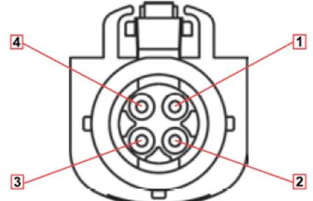
This connector has four pins, but we need two pairs of high speed diff signals and two power line.
I have viewed the TI’s e2e forums websit, and there is the same question about Power over STP. Link as below.
And TI engineer give the below article, it describes the details of Power over FPD-Link concept. Link as below.
https://www.eetimes.com/document.asp?doc_id=1279219
But, if there are some EMI problems when use the braided shield as reference ground?
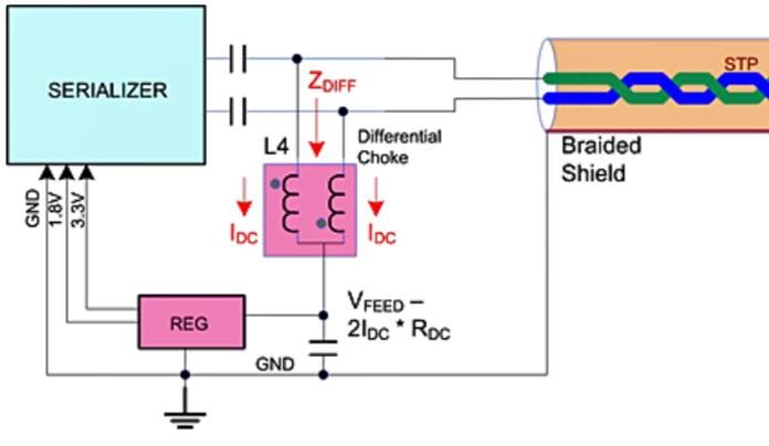
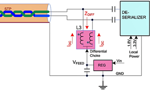
So, Below is our design block diagram.

We use TI’s two chips, ds90ub953 and ds90ub954. In the diagram, we called 953 and 954.
There are two pcb board, 954 and OV491 are on one board, and 953 and OV10640 are on another pcb board.
We use two pins (for example pin 2/4) of STP connector as one diff signal, , simultaneously as the power line. And the other pins 1/3 as another diff signal and reference ground.
In the our design diagram, the power source is from the 954 board, and 953 board sink power.
So, the connector pins 1/3 and 2/4 on the two pcb boards all need some filter parts to split the high speed signals and the DC powers.
Now, we need confirm if this design is feasible and then we should confirm all these filter part’s parameters, such as ferrite bead and inductors.
Thanks!
