This thread has been locked.

If you have a related question, please click the "Ask a related question" button in the top right corner. The newly created question will be automatically linked to this question.

DP83822IF: DP83822 in MII mode with PIC32 (MPLAB Harmony)

Part Number: DP83822IF
Other Parts Discussed in Thread: DP83640

Hi,

I am trying to get a DP83822 phy working with the PIC32MX675F512L

There are two dp phys drivers in MPLAB Harmony, DP83848 and DP83640. I have decided to go for the DP83848 driver as it is most similar to DP83822.

Only 2 functions are to be edited:

  • DRV_EXTPHY_MIIConfigure,
  • DRV_EXTPHY_MDIXConfigure,

I am able to configure the PHY to MII mode (reg 0x0017), configure phy to enable Auto MDI/X (reg 0x0019). I know they're set because when I read these registers back it is what i set them to be. But there are no activity on the ethernet port, which makes me wonder this is a hardware issue.

I have two questions:

Are there any differences in software when initialising the DP83848 and DP83822 in MII mode?

Can you share any schematic examples of the DP83822 in MII (preferably with a pic32)? I can also share schematics of my board, maybe there is a fault you can spot...

Thanks,

Hasib

  • Hi Hasib,

    Can you please share the schematic of the board?

    How are you determining there is no activity on the Ethernet port? Are you viewing LEDs? Are you probing MII RX signals? Are you looking for data using some network tool like wireshark?

    If, when your DP83822 is connected to a known good link partner through a cat5 cable, you see register 0x1bit[2] = 1, then your HW is likely OK. If 0x1.2 = 1 and you don't see Ethernet traffic in your MAC, you likely have a configuration error with your software.

    Best Regards,
  • Hi,

    Thanks for the reply.

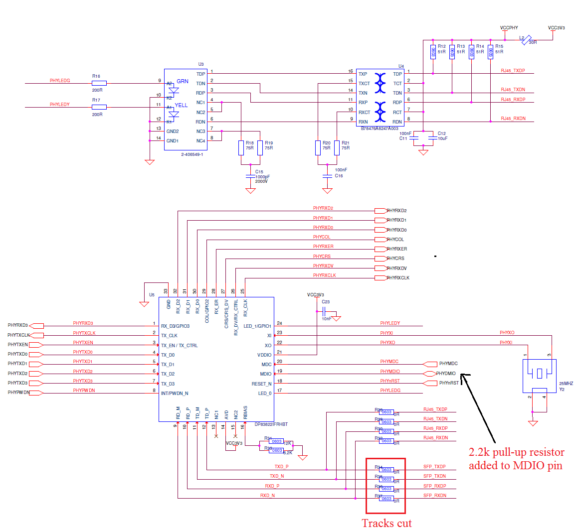
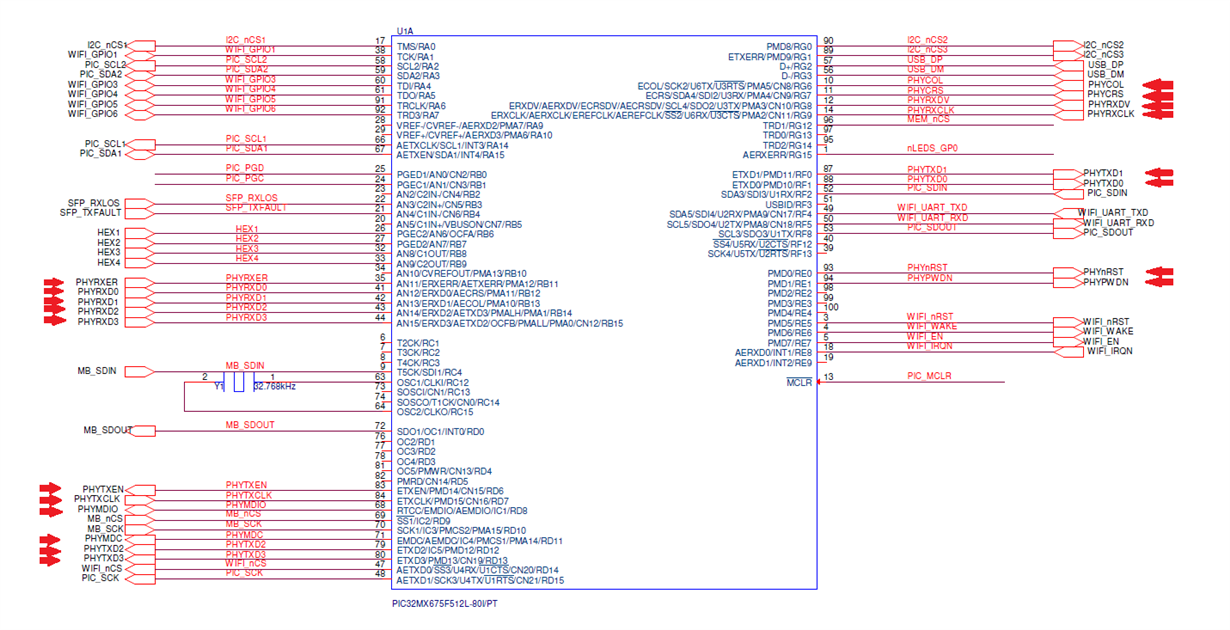
    I have attached the schematics of the phy with the pic32, there are some mods on the phy schematic.

    The green light on the RJ45 pin was initially on but that is because i realised the pin out was wrong in HW. I set LED_0 Polarity bit on reg 0x0018 (LEDCR) and now it is off. 

    Both LEDs are off now... I am using tcpip_discoverer.jar provided by MPLAB Harmony which is used to discover microchip devices in the network. I also do not see any signals when i probe on RX_D0-D2 pins, must there be any pull-ups/ pull-downs in these pins?.

    I would like to mention communication with the phy is established. First I set it to MII mode, second enable LED_0 polarity bit, and third enable Auto-MDIX bit.

    In regards to reg 0x1 bit[2], this is '1' when there is a ethernet cable connected or not. I do however only check this bit while setting the previous 3 bits. 

    Thanks again,

    Hasib

  • Hi Hasib,

    Your RBIAS resistor(parallel combination equivalent) appears to be way off from the required.

    The DP83822 RBIAS resistor must be 4.87k 1%. Without that value connected, the VOD of the signal will be incorrect. The equivalent value you have appears to be 4.087k

    I also don't see any load caps on the crystal. Are there load caps? Your crystal is likely not be oscillating with the PPM requirement of the PHY without load caps. Can you provide a part number for the crystal?

    Best Regards,
  • Hi Rob,

    Thanks for the reply,

    The crystal part number is ABMM2-25.000MHZ-E2-T. I have discussed it with the hardware team and they agree with you. The datasheet for this crystal states it requires a 18pF load cap, can't believe we missed that. The boards will be modified tomorrow to have capacitors in place.

    The two resistors are actually 12k and 8.2k. I think the resolution of the schematics image makes it look like 6.2k which is where i believe you got the value of 4.087k.

    Requiv.= (R1×R2)/(R1+R2) = (12×8.2)/(12+8.2)  = 4.8713k.

    But thanks for noticing the errors. The repairs engineer is off today, I will update the forum tomorrow when the caps are fitted. Hope this is it.

    Regards,

    Hasib

  • Hi Hasib,

    Thanks for the update. The resolution I think was to blame.

    Please keep me updated.

    Best Regards,
  • Hi Rob,

    Still no luck... I have put 18pF caps on  pins 2 and 4 of the crystal and there is still no link.

    Any other suggestions?

    Best regards,

    Hasib

  • Hi Hasib,

    The polarity of the LED pins does not need to be set, and MII and auto-mdix bits are enabled by default if your strapping is correct. Your SW configuration may be unnecessary, so I'd recommend not performing SW configurations at this time.

    One thing to note with DP83822, you must have external pull resistors on the LED pins LED_0 and LED_1 when they are being used as LEDs. Your problem is not likely caused by this issue today, but you will run into a problem if the future if this is not done.

    Your LEDs are connected improperly for mode 4 operation, which is their default operation. I think you discovered that with your polarity reversal, but you may still be causing the PHY to strap into a mode incorrectly.

    If the PHY powers up on a board all alone, with a good power supply and reference input, it will establish link with another PHY. So something that is happening in the system is causing the PHY to behave improperly.

    Register 0x1 bit[2] will = 0 if the PHY is not connected to a link partner, unless the system is placing the PHY into a loopback mode.

    Because you are having so many problems, I suggest taking baby steps here. Try to isolate the PHY. Remove any connections to strap pins and power on the PHY with only MDIO access.

    1. Power up the PHY with NO external connections to a link partner.
    1.a. Verify register 0x1 bit[2] = 0.

    If this bit does not equal 0, you have a problem. Either you aren't talking to the PHY you think you are on the MDIO bus, or you are in a loopback mode, or your MDIO signaling isn't correct.

    2. Connect the PHY to a link partner that is KNOWN GOOD. Your PC is not known good. A router or switch may be a better solution in this case.
    3. Check link in register 0x1 bit[2].

    Then start adding back the system connections once your link is successful.

    Best Regards,
  • Hi Rob,

    Thanks for the reply. 

    The issue with your suggested testing method is I can not remove any connections from the phy unless I cut the tracks from the board completely.

    Can you please draw and attach a simple circuitry for the LEDs to be on mode 4. I will have these mods done to this board, and have them as default in the next spin of the boards.

    I have probed some of the pins and included the screenshots into the attached file. RX and TX clock is at 2.5 MHz when no ethernet cable is connected, but then jumps to 25 MHZ for like half a second when there is some activity in the RD/TD pins, then back to 2.5 MHz for about 2 seconds with no activity in RD/TD pins. This repeats itself... Would you know why this happens?

    MDIO, MDC, XI and XO signal is included in the file. shouldnt XI be 25 MHz?

    Thanks

    Hasib

    8585.dp83822signals.docx

  • Hi Hasib,

    TX_CLK and RX_CLK should be 2.5MHz when no connection is present. This is default 10M mode. When the cable is connected, the PHY is linking to 100M and therefor outputting 25MHz on RX_CLK and TX_CLK. The toggling is suspicious.

    You can redo your measurements with the current limiting resistors pulled out of circuit on the LED pins to see if your link is stable.

    Yes, XI should be 25MHz, but your crystal circuit may not be stable. Loading it with a scope probe can cause oscillation to stop. If your ref clock isn't stable it could lead to significant link issues.

    Best Regards,