This thread has been locked.

If you have a related question, please click the "Ask a related question" button in the top right corner. The newly created question will be automatically linked to this question.

DP83620: The Fiber optic mode of interfacing is not functioning in the PCB after the design

Part Number: DP83620
Other Parts Discussed in Thread: MSP-EXP430F5529LP, USB-2-MDIO

Hello TI,

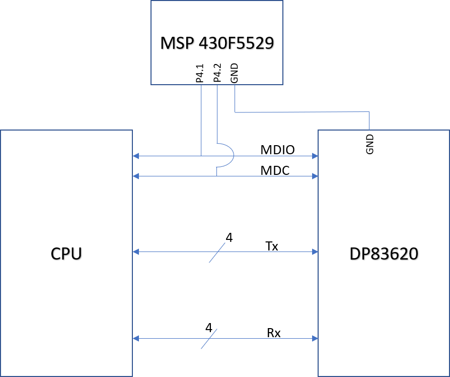
I have used DP83620 in one of our design and and after I received the new boards the Copper mode of the Ethernet is functional whereas the Fiber mode is not functional.

I do have a MSP-EXP430F5529LP development board and believe it could be used to debug the issue by connecting the MDIO and MDC connections.

Kinldy support here.

Since the schematic is a protected document do tell where I can send the it for reference 

  • Hi,

    Kindly share the register dump from 0x00 to 0x31.


    Regards,
    Geet
  • Hello Geet,

    I am getting an error in the USB-2-MDIO tool as "Error! Device is not connected" on the tool as attached.

    Also attaching the image of the MSP dev board for reference.

    Please note that my mother board is operational during this probing.

    Thank you.

  • Geet,
    Any help would be appreciated here..

    Am I connecting the MSP-EXP430F5529LP the right way?
  • This block diagram is representing the way I am connecting the MSP LP with the DP83620.

    Please note that this is just for the MSP LP connection verification, in actual design there are more signals between CPU and DP83620 PHY.

  • You shall isolate both MDC and MDIO from CPU while using MSP430 LP. Otherwise two source are driving the same bus

    Regards,
    Geet
  • Hello Geet.
    I was able to get the register details.

    steps followed:

    - Allowed the board to boot up properly using the MDIO and MDC from the CPU

    - Then connected the MDIO and MDC to the MSP LP board exclusively.

    Attaching the register dump for your reference.

    USB_MDIO Script.txt file is open...
    Register 0000 is: Error occurred for basic read!
    
    Register 0001 is: 0004
    
    Register 0002 is: 0002
    
    Register 0003 is: 0002
    
    Register 0004 is: 0012
    
    Register 0005 is: 0012
    
    Register 0006 is: 0093
    
    Register 0007 is: 009B
    
    Register 0008 is: 0499
    
    Register 0009 is: 0089
    
    Register 000A is: 0049
    
    Register 000B is: 0008
    
    Register 000C is: 0004
    
    Register 000D is: 0004
    
    Register 000E is: 0004
    
    Register 000F is: 0002
    
    Register 0010 is: 0002
    
    Register 0011 is: 0012
    
    Register 0012 is: 0093
    
    Register 0013 is: 0499
    
    Register 0014 is: 0089
    
    Register 0015 is: 0049
    
    Register 0016 is: 0048
    
    Register 0017 is: 0004
    
    Register 0018 is: 0004
    
    Register 0019 is: 0004
    
    Register 001A is: 0000
    
    Register 001B is: 0002
    
    Register 001C is: 0002
    
    Register 001D is: 0012
    
    Register 001E is: 0093
    
    Register 001F is: 009B
    
    Register 0020 is: 0499
    
    Register 0021 is: 0009
    
    Register 0022 is: 0049
    
    Register 0023 is: 0040
    
    Register 0024 is: 0004
    
    Register 0025 is: 0004
    
    Register 0026 is: 0004
    
    Register 0027 is: 0000
    
    Register 0028 is: 0002
    
    Register 0029 is: 0012
    
    Register 002A is: 0012
    
    Register 002B is: 0093
    
    Register 002C is: 009B
    
    Register 002D is: 0499
    
    Register 002E is: 0089
    
    Register 002F is: 0049
    
    Register 0030 is: 0049
    
    Register 0031 is: 0048
    
    End of file.


    Kinldy suggest.

  • Hello Geet,

    Kindly find 2 more register dump files.

    1. PingON_Onboard_20030.txt

    This was taken with the copper mode active and device responding to the ping command.

    USB_MDIO Script.txt file is open...
    Register 0000 is: 1880
    
    Register 0001 is: 78E9
    
    Register 0002 is: 1000
    
    Register 0003 is: 5CE1
    
    Register 0004 is: 00F0
    
    Register 0005 is: CDE1
    
    Register 0006 is: 0007
    
    Register 0007 is: 2801
    
    Register 0008 is: 0000
    
    Register 0009 is: 0000
    
    Register 000A is: 0000
    
    Register 000B is: 0000
    
    Register 000C is: 0000
    
    Register 000D is: 0000
    
    Register 000E is: 0000
    
    Register 000F is: 0000
    
    Register 0010 is: 240A
    
    Register 0011 is: 0000
    
    Register 0012 is: 1600
    
    Register 0013 is: 0000
    
    Register 0014 is: 0018
    
    Register 0015 is: 0000
    
    Register 0016 is: 0080
    
    Register 0017 is: 0001
    
    Register 0018 is: 0000
    
    Register 0019 is: 803E
    
    Register 001A is: 0402
    
    Register 001B is: 0000
    
    Register 001C is: 0001
    
    Register 001D is: 6011
    
    Register 001E is: 041F
    
    Register 001F is: 0000
    
    Register 0020 is: 1880
    
    Register 0021 is: 78ED
    
    Register 0022 is: 1000
    
    Register 0023 is: 5CE1
    
    Register 0024 is: 00F0
    
    Register 0025 is: CDE1
    
    Register 0026 is: 0006
    
    Register 0027 is: 2801
    
    Register 0028 is: 0000
    
    Register 0029 is: 0000
    
    Register 002A is: 0000
    
    Register 002B is: 0000
    
    Register 002C is: 0000
    
    Register 002D is: 0000
    
    Register 002E is: 0000
    
    Register 002F is: 0000
    
    Register 0030 is: 1880
    
    Register 0031 is: 78ED
    
    End of file.


    2. FO_Onboard_20030.txt

    This was taken when the IC was configured for the Fiber Optic mode of interfacing.

    USB_MDIO Script.txt file is open...
    Register 0000 is: 366D
    
    Register 0001 is: 6CDB
    
    Register 0002 is: 6CDB
    
    Register 0003 is: 26CD
    
    Register 0004 is: 66DD
    
    Register 0005 is: 26CD
    
    Register 0006 is: 36ED
    
    Register 0007 is: 1366
    
    Register 0008 is: 1366
    
    Register 0009 is: 1B36
    
    Register 000A is: 1B36
    
    Register 000B is: 99B6
    
    Register 000C is: 4DBB
    
    Register 000D is: 4DBB
    
    Register 000E is: 4D9B
    
    Register 000F is: 6CDB
    
    Register 0010 is: 26DD
    
    Register 0011 is: 366D
    
    Register 0012 is: 1B76
    
    Register 0013 is: 1B36
    
    Register 0014 is: CDB3
    
    Register 0015 is: 1B36
    
    Register 0016 is: D9B7
    
    Register 0017 is: 4DBB
    
    Register 0018 is: 4D9B
    
    Register 0019 is: 4D9B
    
    Register 001A is: 6CDB
    
    Register 001B is: 26CD
    
    Register 001C is: 26CD
    
    Register 001D is: 26CD
    
    Register 001E is: 26CD
    
    Register 001F is: 1366
    
    Register 0020 is: 136E
    
    Register 0021 is: 1B36
    
    Register 0022 is: 1B36
    
    Register 0023 is: 366D
    
    Register 0024 is: 336C
    
    Register 0025 is: 1B36
    
    Register 0026 is: 1B36
    
    Register 0027 is: C9B7
    
    Register 0028 is: 6CDB
    
    Register 0029 is: 6EDB
    
    Register 002A is: 26DD
    
    Register 002B is: 336C
    
    Register 002C is: 336C
    
    Register 002D is: 366D
    
    Register 002E is: 366D
    
    Register 002F is: 366D
    
    Register 0030 is: 366D
    
    Register 0031 is: 366D
    
    End of file.


    It will be very helpful,If you could provide me a contact number or email for the direct communication with this support as project timelines are getting affected.

    Thank you.

  • Hi,

    In FO_Onboard_20030.txt, Register 0x16 bit[6] indicates Fiber mode thru strap selection. In register dumps its reading 0xD9B7. Bit[6] is 0 while it shall be '1'. Can you check your straps are correct ? Otherwise you can also force this bit thru MDIO and perform soft reset.

    Regards,
    Geet
  • Hello Geet,
    Thank you for the response.
    About the register 0x16, it is not getting stable and i am getting different values each time, hence how can I confirm the strapping options?

    Register 0016 is: 64D9
    Register 0016 is: 1936
    Register 0016 is: 26CD
    Register 0016 is: 89B2
    Register 0016 is: 1936
    Register 0016 is: 326C
    Register 0016 is: 1364
    Register 0016 is: 4993
    Register 0016 is: 4993
    Register 0016 is: 1936
    Register 0016 is: 6C9B
    Register 0016 is: 64DB
    Register 0016 is: 1326
    Register 0016 is: 326C
    Register 0016 is: 4D9B
    Register 0016 is: 1936
    Register 0016 is: 64DB
    Register 0016 is: 1936
    Register 0016 is: 1326
    Register 0016 is: 1326
    Register 0016 is: 264D
    Register 0016 is: 64DB
    Register 0016 is: 49B3
    Register 0016 is: 1264
    Register 0016 is: 1366
    Register 0016 is: 64D9
    Register 0016 is: 64D9
    Register 0016 is: 1326
    Register 0016 is: 264D
    Register 0016 is: 326D
    Register 0016 is: 264D
    Register 0016 is: 49B3
    Register 0016 is: 64DB
    Register 0016 is: 4C9B
    Register 0016 is: 264D
    Register 0016 is: 4C9B
    Register 0016 is: 49B3
    Register 0016 is: 226C
    Register 0016 is: 226D
    Register 0016 is: 126C
    Register 0016 is: 64DB
    Register 0016 is: 4C9B
    Register 0016 is: 126C
    Register 0016 is: 266D
    Register 0016 is: 1B36
    Register 0016 is: 26CD
  • Hi,

    Bit 6, 3, 1, 0 shall not change as it is latched thru straps.

    Regards,
    Geet
  • Geet,

    I understand the above.

    To ease the debugging, i moved to the my DP83620 Eval kit and i found that the 0x16 has a consistent value on the eval board for the FO mode i.e. 014B however the response of the Eval board is same a the newly designed board where the link LED is turned on but there is no data transmission.

    Attaching the register dump of the eval kit.

    USB_MDIO Script.txt file is open...
    Register 0000 is: 2100
    
    Register 0001 is: 78CD
    
    Register 0002 is: 2000
    
    Register 0003 is: 5CE1
    
    Register 0004 is: 0101
    
    Register 0005 is: 0000
    
    Register 0006 is: 0004
    
    Register 0007 is: 2001
    
    Register 0008 is: 0000
    
    Register 0009 is: 0000
    
    Register 000A is: 0000
    
    Register 000B is: 0000
    
    Register 000C is: 0000
    
    Register 000D is: 0000
    
    Register 000E is: 0000
    
    Register 000F is: 0000
    
    Register 0010 is: 0005
    
    Register 0011 is: 0000
    
    Register 0012 is: 2000
    
    Register 0013 is: 0000
    
    Register 0014 is: 0000
    
    Register 0015 is: 0000
    
    Register 0016 is: 014B
    
    Register 0017 is: 0001
    
    Register 0018 is: 0000
    
    Register 0019 is: 003E
    
    Register 001A is: 0804
    
    Register 001B is: 0000
    
    Register 001C is: 0002
    
    Register 001D is: 6011
    
    Register 001E is: 089E
    
    Register 001F is: 0000
    
    Register 0020 is: 2100
    
    Register 0021 is: 78CD
    
    Register 0022 is: 2000
    
    Register 0023 is: 5CE1
    
    Register 0024 is: 0101
    
    Register 0025 is: 0000
    
    Register 0026 is: 0004
    
    Register 0027 is: 2001
    
    Register 0028 is: 0000
    
    Register 0029 is: 0000
    
    Register 002A is: 0000
    
    Register 002B is: 0000
    
    Register 002C is: 0000
    
    Register 002D is: 0000
    
    Register 002E is: 0000
    
    Register 002F is: 0000
    
    Register 0030 is: 2100
    
    Register 0031 is: 78CD
    
    End of file.


    if you can let me know the issue for the eval board data above may be i could use the same learning on the newly designed board.

    Thank you.

  • Hello Geet,

    For the Eval board the value of register 0x14 on the Page 2 i.e LEN100_DET shows 00FF.

    The datasheet specifies that FF value from 7:0 indicates that the cable length cannot be determined.

    Can this be a reason why it is not working even on the development board even though the FO cable is connected on the connector???

    Kindly suggest.

  • Hi Chitransh,


    Register 0x10 do indicate 100M Link-Up. Now, can you explain how you are connecting the EVM to transfer the data ?

    Some of the basic things we check is
    - RX_CLK clock is 25 MHz, given link is 100M
    - RX_DV and RX_Dx shall toggle when recieving the data.


    LEN100_DET is for cable diagnostics for Copper only. These are not applicable for Fiber as transmission on actual cable is managed by FO.


    Regards,
    Geet
  • Hi,

    I am closing this thread. Incase you have further queries, please open new thread and provide reference to this thread.

    Regards,
    Geet
  • Hello Geet.
    I was an issue with the branching IC that I was using to fan out the Copper mode and Fiber mode signal.

    Issue is now resolved.

    Thank you..

  • Hi Chitransh,

    Good to hear that. You mea you are usig same PCB to enable both FIber and Copper mode signals ?

    Regards,
    Geet