Hello Nasser,
Here is related question of LMH1983 Lock detection scheme.
Our customer's product got filed issue, it has Pin11 No_Lock = H behavior even inputted very clean signal, PLL is always Locked.
They had found workaround that is increasing the value of Loss of Lock Threshold (Register 0x1C). However we could reach theoretical mechanism of this workaround effectiveness.
Could you read following little bit longer message, we thank for your help in advance.
<< LockStepSize setting >>
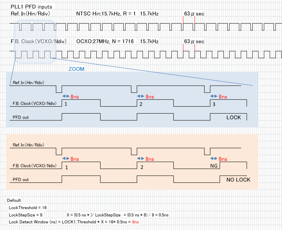
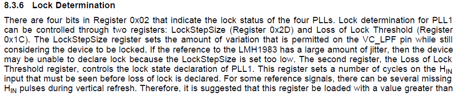
On datasheet page16, section 8.3.6:
...LockStepSize (Register 0x2D) and Loss of Lock Threshold (Register
0x1C). The LockStepSize register sets the amount of variation that is permitted on the VC_LPF pin while still
considering the device to be locked....
Qestion1: Could you elaborate Threshold of actual number of plus count at VC_LPF pin outputted pulse detect to?
On datasheet page31, Register Map of 0x2D:
4:0 Lock Step Size R/W 01000 See Application Information section discussion on Lock Detect
Question 2: Where is the location of "Lock Detect discussion" in the link of "Application Information"?
We could not find additional information in datasheet. Is there another document?
<< Lock Threshold setting>>
On datasheet page16, section 8.3.6:
The second register, the Loss of Lock Threshold register, controls the lock state declaration of PLL1. This register sets a number of cycles on the HIN input that must be seen before loss of lock is declared. For some reference signals, there can be several missing HIN pulses during vertical refresh. Therefore, it is suggested that this register be loaded with a value greater than six (Loss of Lock Threshold > 6).
On one datasheet page30, Register Map of 0x1C:
0x1C Loss of Lock Threshold
Sets the number of Hsync periods to wait before setting loss of lock. Since during blanking there can have up to 5 missing Hsync pulses, this value is usually set > 6.
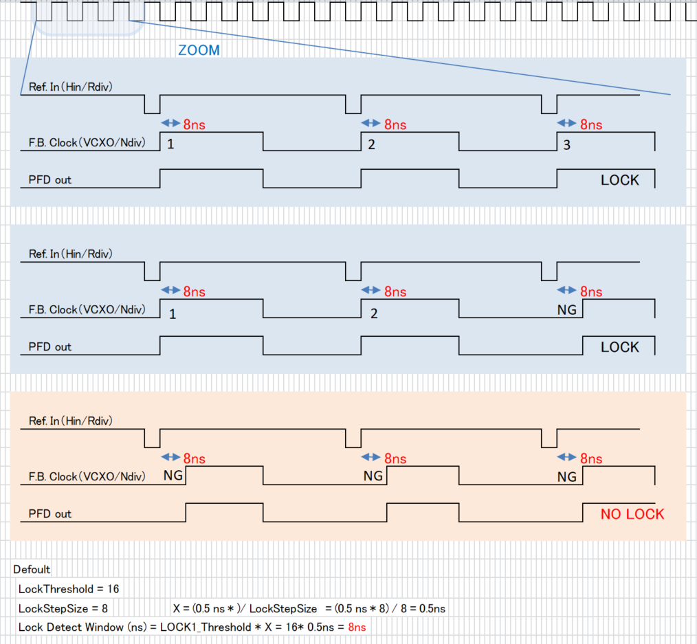
In your previous e2e reply:
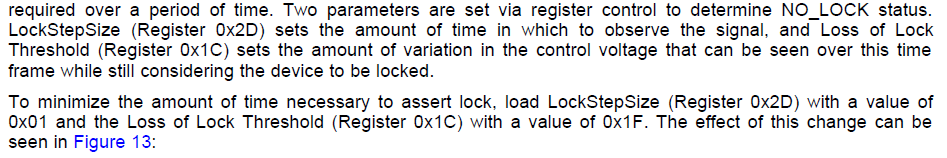
What the datasheet is explaining is that to make the LOCK determination time the fastest, you load LOCK STEP_SIZE with a 1 (minimum amount of time to look at pulses) and LOCK_THRESHOLD with a 31 which is a large number, indicating that even if there is significant activity, the device should declare LOCK.
Question 3: Are those statement saying same behavior? Following your e2e description, our understanding is that the value of "Loss of Lock Threshold" is time domain window of pulse count measurement at the VC_LPF pin. Unit of time window is Hsync periods. Is that correct? Then what is the relation between the statement of "Sets the number of Hsync periods to wait before setting loss of lock." on the datasheet?
It seems value of "Loss of Lock Threshold" is just Waiting time to set Loss of Lock register after detected certain number of plus at VC_LPF pin. There looks no function of plus measurement "time window". Would you please summarize those three descriptions and re-describe "Loss of Lock Threshold" function in simple words?
Regards,
Mochizuki