HI there,
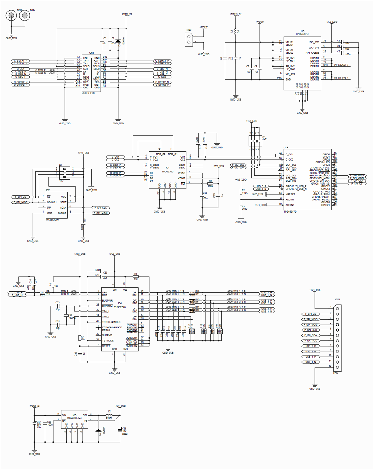
I have built the TPS65987D into my design, the aim being to create a USB-C UFP, (sink only), that can negotiate up to 20V and 2.25A from a USB-C power source.
Firstly, when I plug my design in using the USB-C cable, and when interrogating it through I2C or SPI (using a TPS65981-EVM's FTDI programming module) - it seems to be readable and behaving as expected, and I can see the PD advertised by the power supply is read by the TPS65987D, using the TPS6598x Utilities GUI software.
However, it does not seem to negotiate for the 20V supply, even though I have set the ADCIN1 resistor-divider network and MISO=0 on bootup - which is the first thing that concerns me.
So in order to fix this, I have attempted to create my own application-specific version of the firmware using the Application Customisation Tool, version 5.1. However, when I flash this to the device (over SPI), it seems to be successful, but then the device seems to stop functioning. I can no longer see the "APP" firmware running on (this is now blank), and no I2C channel will respond. When I do an I2C scan, it reports that every I2C address replies (instead of just one or 2 as it should), and of course none of these work correctly.
I attempt to re-flash with the EVAL recovery .bin, but the same thing occurs and the device seems unusable still.
Can you please advise, or notify me of what I am doing wrong? In reality I don't want to do anything complex, just negotiate a higher voltage and current, so a custom application is hopefully not necessary, but I'd still like to be able to understand and recover the device.
Thanks,
Iain.


