This thread has been locked.

If you have a related question, please click the "Ask a related question" button in the top right corner. The newly created question will be automatically linked to this question.

SN75178B: SN75178B

Part Number: SN75178B
Other Parts Discussed in Thread: THVD1451, THVD1500, THVD1550, THVD1551, ISO3082

Hi Team,

We are planning to use TI's SN75178B RS485 Repeater in our design.

We are developing a RS485 Multi-drop board design. So we have few clarifications with respect to the above mentioned part:

- Whether we can use SN75178B without any issues ? If so, how many repeater ICs we need per board for bi-directional communication (considering 20 RS485 slaves per board) ?
- Is there application note available for this part or for any other RS485 Repeater from TI ?
- Please suggest if any other better part is available with TI

Our requirements are as below:
Application: Sensor data transmission
Channel: 1/1 (1 driver, 1 receiver)
Communication: Full Duplex
Data rate: 10 Mbps
Length: around 100 feet
DRIVER/RECEIVER ENABLE: Optional

Best Regards,
Madhusoodana Bairy

  • Madhusoodana,

    I don't see any issues of using SN75178B as a repeater. If it's possible, could you share the system diagram? Do you mean 20 slave nodes needs to be supported on each board? SN75178B can work with up to 32 nodes.

    Another choice is THVD1451, which works with 3.3V to 5V supply and has better ESD performance.

    Unfortunately there are not much application notes on this topic. You can take a look at this 8713.Data-Rate Independent Half Duplex Repeater Design for RS-485.pdf about half-duplex repeater.


    Regards,
    Hao

  • Hi Hao,

    Thanks for your response.
    I have not prepared any system diagram yet and working on the same now. I should be able to share in a couple of days.
    Yes, 20 slave nodes needs to be supported on each board.
    By the way how many repeater ICs we may need per board for bi-directional communication (considering 20 RS485 slaves per board) ?

    Best Regards,
    Madhusoodana Bairy
  • Madhusoodana,

    One of options is to have 2 RS-485 transceivers on each board. The communication between boards are RS-485. The second RS-485 drives the slaves on the board. But I would like to see your system design to make sure I understand the application. BTW, why do you need repeaters, to extend distance or to support more nodes?

    Regards,
    Hao
  • Hi Hao,

    Is there any difference between a RS-485 transceiver and a repeater ? How many ICs I may need to use if I use SN75178B part in my board ?

    Sure, i will try to send the diagram by Monday. I need RS-485 transceiver or a repeater to extend the nodes (20 per board). Distance will be in tens of inches and not more than that.

    Best Regards,
    Madhusoodana Bairy

  • Madhusoodana,

    How many boards do you have in total? Many latest RS-485 transceivers support up to 256 nodes, such as THVD1500, THVD1550.

    Regards,
    Hao
  • Hi Hao,

    We have total of 4 boards, each having 20 slaves (20x4=80 slaves in total).

    What is the difference between RS-485 transceiver and a Repeater ? As per my understanding, we need only one IC if we use ‘repeater’ instead of RS-485 transceiver. Is this understanding correct ?

    Best Regards,
    Madhusoodana Bairy

  • Madhusoodana,

    I'm sorry my answer several days didn't show up somehow. In general, if the communication distance is too long or there are too many nodes, you may need a 'repeater' function, which is composed by one receiver and one transmitter. The receiver converts RS-485 signal to TTL then the transmitter converts this TTL to start another segment of RS-485. Your understanding is correct. SN75178B integrates this two into one device, or you could use two basic transceivers to implement the same function.

    Regards,
    Hao
  • Hi Hao,

    No problem.
    Thanks for the details. But when I searched for repeater parts from TI, I got only SN75178B which is quite old as well. Is there any other repeater parts available from TI ?

    Because I think we may need some additional circuits like isolation, time delay circuit etc if we are designing a repeater circuit through 2 transceivers. Am I correct ?

    If there are repeater parts from TI, is there any other advantage for using repeater instead of transceivers ?

    Best Regards,

    Madhusoodana Bairy

  • Hi Madhusoodana,

    Hao is out of the office at the moment, so I will try to help.

    Within the scope of RS-485 devices, the term transceiver means a device with a transmit function (that converts single-ended logic-level signals to differential bus signals) and a receive function (that converts differential bus signals to single-ended logic-level signals). If the differential transmit and receive signals are shared on a common pair of wires the circuit is considered half-duplex, and if the transmit and receive pairs are separated then the circuit is considered full-duplex.

    The SN75178B is equivalent to a receiver whose logic output is tied to a transmitter (which then re-transmits whatever signal is received). This same function could be implemented with two half-duplex transceivers (like THVD1550) or a single full-duplex transceiver (like THVD1551) - in either case, the "R" output of the receiver circuit would be tied to the "D" input of the transmitter circuit. Extra components would not be needed unless these are required for other reasons (for example, the application may require galvanic isolation due to safety concerns, etc.).

    Dedicated repeater parts are not all that common because (1) this function is easily achieved via transceiver devices, (2) most RS-485 networks don't require repeaters since the standard supports communication among a large number of nodes over long distances, and (3) the majority of networks use a single-pair half-duplex signaling scheme in which the direction of data flow needs to be controlled and thus simple repeater circuits could not work. (An example half-duplex repeater was provided in Hao's link above - note the added complexity required to handle the driver/receiver enable control lines.)

    I hope this helps to clarify - please let us know whatever further questions you have.

    Regards,
    Max
  • Hi Max,

    Thanks for your response.

    I have following 2 questions:

    1. I think even though if I use full-duplex transceiver (like THVD1551), i need two numbers of this to achieve the 'repeater' functionality. 1st device converts RS-485 to UART, so I need one more to convert this UART back to RS-485 before feeding next set of slaves (which are in other board), correct ?

    2. When I may need a time-delay circuit ? Because the reference design of ISO3082DW has used this circuit between 2 nos. of this device (file named 'TI Designs: Dual Isolated Half-Duplex RS-485 Repeater.pdf').

    Best Regards,

    Madhusoodana Bairy

  • Madhusoodana,

    Since the THVD1551 implements both receive (RS-485 to CMOS/TTL) and transmit (CMOS/TTL to RS-485) functions, only a single chip would be needed to realize a repeater function. The A/B pins would receive the RS-485 data and output it on R. The R pin can then be connected to the D input pin, which would then output onto the Z/Y RS-485 outputs.

    The timing circuit is required only in half-duplex networks. Since half-duplex signaling uses the same differential pair for both receiving and transmitting, the user needs to be careful not to have more than one transmitter circuit enabled at any given time (or else the multiple transmitters will interfere/contend with one another and corrupt the data). Because of this, it is critical to properly control the "enable" inputs of a transceiver. Typically a node will remain in a "listening" mode with its transmitter disabled and receiver enabled until it is time to transmit a word or frame, then switch into a "transmit" mode (with driver enabled). Often times this requires a UART or MCU to control the "DE" and "/RE" inputs to the transceiver along with the "D" and "R" lines that are used to send and receive the actual data. The reference design you mentioned uses a timing circuit to control the "DE" and "/RE" signal automatically, though, without requiring an MCU. (It does this by enabling the driver whenever the "D" line toggles.)

    For full duplex applications, the direction of data flow on each pair of wires is fixed and so one side is always a transmitter and the other side is always a receiver. So, this extra enable control circuit is not needed.

    Please let me know if this isn't clear.

    Regards,
    Max
  • Hi Max,

    Thanks for your response.

    We are using Full Duplex communication and so there are 2 pairs (4 individual lines or 4-wire mode) of differential signals. But the THVD1551 part has 1 TX+/- & 1 RX+/- pins. How we can pass our TX+/- & RX+/- signals from the last node through this transceiver and feed to the next set of slaves (I am talking about pin connections and its inputs/outputs here). It would be helpful if you can share any application design/circuit for any Full Duplex transceiver used as a repeater or for repeater functionality (I got one with ISO3082 but it is a half duplex application).

    Best Regards,
    Madhusoodana Bairy
  • Madhusoodana,

    I misunderstood your application. If you need a repeater for two different directions (e.g., transmit and receive) then you are correct that you would need two THVD1551 devices (one for each direction). This would be the same for the SN75178B.

    Regards,
    Max
  • Hi Max,

    Thanks for your response.

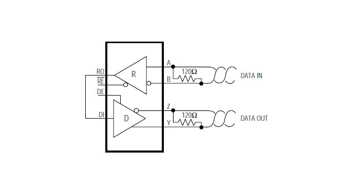
    If I use a 2/2 transceiver (2 drivers/transmitters & 2 receivers), then I should be able to use only 1 transceiver chip right ? (if I can feed the data into the receiver & take the data out from the driver, as in the image below).

    Best Regards,

    Madhusoodana Bairy

  • Madhusoodana,

    The image above is the circuit I was trying to describe using THVD1551. This will "repeat" the signal in one direction - i.e., it will receive from one side and transmit the same bit to the other side. If you had an additional channel with the same configuration then it could also repeat a differential pair communicating data in the other direction.

    Max
  • Hi Max,

    Thanks for your response.
    It would be helpful if you can share any application design/circuit for any Full Duplex transceiver used as a repeater or for repeater functionality (I got one with ISO3082 but it is a half duplex application).

    Best Regards,
    Madhusoodana Bairy

  • Madhusoodana,

    There is more reference material around the half-duplex implementation because of the complexity of the additional timing circuits. There isn't a reference for the full-duplex implementation since it is substantially simpler; it would just match the circuit shown above.

    Max
  • Hi Max,

    Thanks for your response.
    Sorry, I still have few generic questions, as below:

    1. How much load capacitance a RS-485 master can drive? What is the typical capacitance of a transceiver ?

    2. Whether all RS485 transceivers support ModBus protocol ?

    3. If we have a board-to-board connection and if each board has around 20 salves, connected in Daisy chain manner, whether the board-to-board connection through the repeater and then to the next board through a connector still will be in Daisy chain !? (total 20X4 boards = 80 slaves)


    Best Regards,
    Madhusoodana Bairy

  • Madhusoodana,

    Typical transceiver capacitance is small (<50 pF). In many cases it's the parasitic capacitance of the cabling that dominates the total load capacitance of the network. Since most RS-485 drivers are fairly strong several nF of load capacitance often can be tolerated. Of course, since this impacts the timing of the signals and so it will depend on the maximum bit rate used. If you wanted to do a rough calculation, I'd recommend assuming a driver circuit has an output impedance on the order of 50 Ohms and using this value with the load capacitance to estimate the time constant of the system. This should be much less than the time required for one bit.

    Yes, any RS-485 compliant transceiver can be used with the ModBus protocol. RS-485 serves as the physical layer, while ModBus defines a higher-layer protocol.

    I'm having a little difficulty understanding your third question. If the there is an "input" port that takes in the data and routes it to each slave on the board in a daisy chain fashion and then an "output" port that would distribute it to the next node, then the nodes could be connected in a daisy chain as well. In this case, the entire network would be a daisy chain. Let me know if that doesn't answer you.

    Regards,
    Max
  • Hi Max,

    Thanks a lot for your response. Now I got it.

    Regarding the 3rd question, yes you are right in the understanding. But looks like I can not use the same pins (of the connector) to route it to the next board. Because this will form a star topology I guess, whereas we need daisy chain.

    Also, can you get me any one design/application circuit WITH MANY RS-485 NODES / SLAVES (at-least 10 nodes) for repeater functionality ?

    Best Regards,

    Madhusoodana Bairy

  • Madhusoodana,

    I'm unfortunately not aware of such a reference design. Actually, it is not all that common to introduce repeaters to achieve these node counts since many RS-485 transceivers are available that can support >100 nodes (for example, THVD1551 supports up to 196 nodes based on the input leakage performance). Repeater circuits are more common when a daisy-chain topology is not feasible, since it helps to mitigate the signal integrity impairments that would otherwise show up as a result of long, unterminated stub nodes (that may be present in a star or tree type topology, for instance).

    Regards,
    Max
  • Hi Max,

    Thanks for your response.

    I hope this will be my last query on this:

    What is the use of isolation circuit which is used in few reference designs of repeaters ? I guess this is for isolation between different nodes in the bus, since it is in daisy-chain (any one device failure affects others).

    Best Regards,
    Madhusoodana Bairy

  • Madhusoodana,

    People introduce isolation barriers for various reasons. One is, as you've mentioned, fault confinement - i.e., preventing potentially hazardous fault conditions from effecting downstream circuitry. This may be either out of concern for safety of a human operator or simply concern for more sensitive electronics.

    Another reason isolation may be introduced is to help communicate between nodes that operate from independent power circuits. In this case, there could be a difference in ground reference potentials from node to node. Small differences can be handled without isolation (since these manifest as common-mode deviations on the RS-485 bus, and the RS-485 standard defined operation over a -7 V to +12 V common mode range), but for larger offsets it can be useful to introduce isolation. Section 11 of this application note gives a good overview of this: www.ti.com/.../slla272c.pdf.

    Regards,
    Max
  • Hi Max,

    Thanks for your response.

    Can we feed in RS-485 differential data to a transceiver, then convert to UART, then feed to the next transceiver's UART pins and take out differential data ?
    I hope no any problem with this circuit. Attached the circuit i am explaining (for a Full-Duplex repeater). Please suggest if it is of any concern.

    Best Regards,
    Madhusoodana Bairy

  • Hi Max,

    Attachment, if it is not displayed in the previous post.

    Best Regards,

    Madhusoodana Bairy

    Repeater circuit.pptx

  • Madhusoodana,

    Yes, the circuit you've shown will work for a bidirectional, full-duplex repeater.

    Since, your application involves a daisy-chain (series) connection, you will not be wiring these repeaters in "parallel" such that the Y/Z outputs of one connect directly with the Y/Z outputs of another, correct?

    Max
  • Hi Max,

    Thanks for your response.

    Yes, you are absolutely correct. Because of the routing topology (Daisy chain) needed, I have not connected Y/Z outputs together.

    I forgot to mention about the protocol. We are going to use ModBus protocol. I am new to ModBus. Do you see any possible issues for using ModBus protocol for around 80 slaves connected in Daisy chain manner ??

    Best Regards,
    Madhusoodana Bairy

  • Madhusoodana,

    The ModBus protocol can support up to 256 nodes, so 80 would be no problem as long as the physical layer implementation (transceivers used, cabling, etc.) is not a limiting factor.

    Max
  •  Hi Max,

    Thanks for your response.

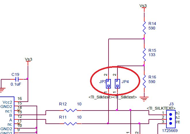
    Adding jumpers on RS-485 differential signals (for enabling & disabling termination resistors) mismatches impedance ? Please refer red oval in the attachment, just for an example.

    Since our operating speed is 10 Mbps only, I guess this will not be a problem.

    Best Regards,

    Madhusoodana Bairy

  • Madhusoodana,

    As long as you can keep those traces on the PCB relatively short (and similar in length between A and B lines), then the effects of this jumper should be minimal.

    Max
  • Hi Max,

    Thanks for your response.

    Best Regards,

    Madhusoodana Bairy