A related question is a question created from another question. When the related question is created, it will be automatically linked to the original question.
If you have a related question, please click the "Ask a related question" button in the top right corner. The newly created question will be automatically linked to this question.
Can you be more specific about the failure? Are you getting no image on your display, or is there an image but it is incorrect/distorted? What resolution/clock frequency is this application? Have you checked the input/output signals (clock, data, etc.) for irregularities? Have you tried multiple units?
There is no image on display. Input signals tested and they are proper. But ground plane (for LVDS GND, PLL GND and GND) is common. I think these ground plane should be separate.
The grounds should be common.
Is the DS90CF384A integrated in the panel? or are you hard wiring?
When you state "proper" all we know is that it is toggling. This tell you nothing about the mapping.
You need to double check the mapping of the signal from the input of the serializer (not stated) to the mapping of the output of the deserializer.
This is what I think is the problem is.
Input for DS90CF384A is connected with shielded LVDS cable. Output is connected to RGB interface display. This IC is assembled on separate PCB.
Input LVDS signals pair connected to respective RxIN pins. Input LVDS CLK input are connected to RxCLKIN pins. These LVDS signals are coming from PC motherboard.
Output RGB signals are connected with reference to datasheet (Figure 4. “16 Grayscale” Test Pattern (DS90CF384A)).
Hi Sandeep,
I looked at the scope shot you provided but this doesn't make sense to me. Why is the RxCLK OUT clock toggling from 1.2V to 2.1V. The 384 output should toggle 0 to 3.3V (nom).
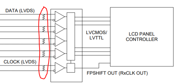
In addition, I just noticed that you are not terminating the LVDS inputs in your schematic. The DS90CF384A requires 100 ohm differential termination resistors on the LVDS data lanes and LVDS clock lane, as close to the device inputs as possible:
Please add these resistors and check if the problem still persists.