This thread has been locked.

If you have a related question, please click the "Ask a related question" button in the top right corner. The newly created question will be automatically linked to this question.

CCS/TCA9803: I2C probelm, DSP as a master and I2C LCD as a slave

Part Number: TCA9803

Tool/software: Code Composer Studio

I want to implement an I2C signal buffer to drive my I2C LCD.

The reason is that without the buffer, the DSP 28020 GPIO is not powerful to drive it.

You can see the waveform below. Rise time is not decent.

Code is successfully generated. 0x7C(slave address), 0x80, 0x28 are sent with a stop on the DATA wire. 

After I add the I2C signal buffer chip, LCD is not properly initialized. 

Because the waveform now looks like this (probe on TCA9803 output)

DSP is only able to send the first byte, 0x7C, the rest 2 bytes are missing and no stop condition is generated. 

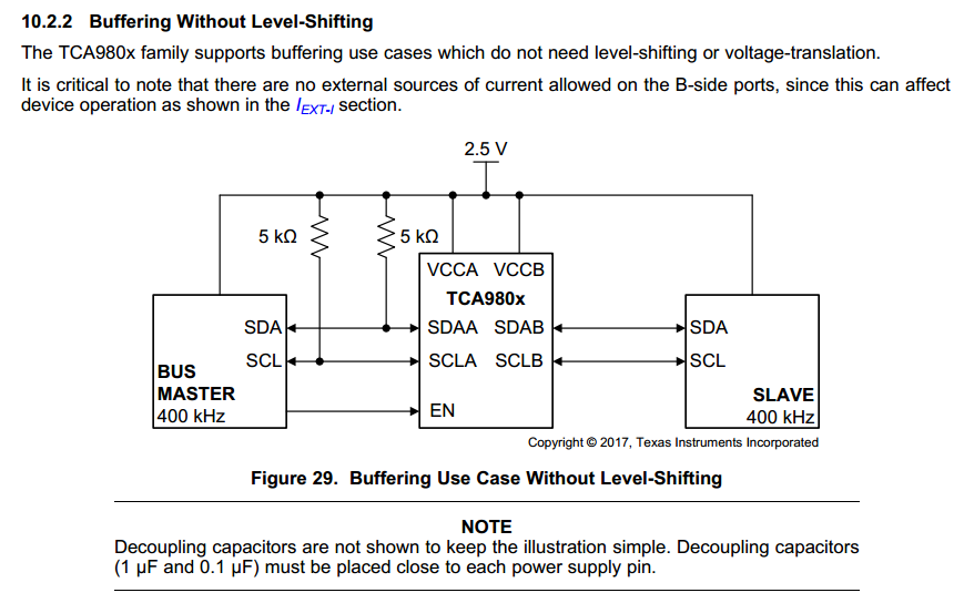
The buffer chip I use is TCA9803 from TI, and the circuit schematic is here.

I use 3.3V here. EN is directly connected to 3.3V. 

Q1: I guess it is a hardware problem. Can anyone help me with this?

Q2: If I choose to drive my LCD by DSP directly, what is the right schematic? Do I connect SDA and SCL to LCD port without other component? or I need to add two pull up resistors for SDA and SCL wire?

  • Hi Xiaoming,

    I agree it looks like a hardware issue which seems to begin with the ACK bit of the first transaction, so let me first make sure I understand your set-up.  Does your schematic exactly match the datasheet screenshot above (except with VCC = 3.3 V)?  And, is the DSP acting as "master" on the A side and the LCD as "slave" on the B side?  Are there any pull-up resistances on the B side (for example, ones integrated into the LCD)?  Is the DSP configured for "open drain" type outputs (i.e., the low level is strongly driven but the high level is high impedance) or is it configured for "push pull"?

    Where are the waveforms being measured - on the DSP side or the LCD side?

    To answer your other question about the direct connection - I2C uses open-drain signaling in order to achieve bidirectional communication, and so generally pull-up resistances are required.

    Regards,
    Max

  • Hi Max,

    Let me first answer your questions first then I describe the updates. 

    Q: Does your schematic exactly match the datasheet screenshot above (except with VCC = 3.3 V)? A: VCC is 3.3V, EN is directly connected to 3.3V, all the other parts are exactly matched.

    Q: Is the DSP acting as "master" on the A side and the LCD as "slave" on the B side? A: yes.

    Q: Are there any pull-up resistances on the B side (for example, ones integrated into the LCD)? A: I don't know. I attach a datasheet of the LCD for your reference.LCD Datasheet.pdf

    Q: Is the DSP configured for "open drain" type outputs? A: DSP GPIO is configured internal pull up resistor enable. 

    Q: Where are the waveforms being measured - on the DSP side or the LCD side? A: LCD side. TCA9803/LCD side. 

    Updates: 

    I find the hardware reason of rise time issue. Now I remove the capacitors on the I2C bus wire and now the rise time looks good(DSP drives LCD directly, TCA9803 is not used). 

    I also tried disable internal pull up and added 2 3.6kohm external pull up resistors(I did not find a 5.1kohm). The rise time is even better(DSP drives LCD directly, TCA9803 is not used).

    For the TCA9803, it is not easy to reach master/buffer interface so I am not able to provide you a screenshot. 

    One more question, I use I2C function in a very bad EMI Environment. There is a ~30kHz resonant converter close to the I2C port and the DSP. I want to use LCD to display converter's operation status but it goes no responding easily (few seconds after the converter starts) so I guess the I2C signal is interfered. Do you know any way to counteract EMI or refresh/reconnect the I2C device?

    Thank you!

    Regards,

    Xiaoming

  • Hi Xiaoming,

    It sounds like your interface works OK without a buffer device, but if you would like to further debug the issue you saw with the TCA9803 just let me know.

    In general open-drain interfaces can be more susceptible to EMI due to the weak biasing of the high-level voltage.  Using a smaller pull-up resistance and some filtering capacitance can help with this, but would affect signal levels and timing as well (and so there are limits to the values that can be used).

    There are some techniques for resolving a locked up bus as well.  Usually when this occurs it is because a slave device becomes out of sync with the master clock (for example, due to missing an SCL clock pulse).  This can cause it to be stuck at a low level (preventing further communication on the bus) even after the byte transfer is supposed to be complete.  This situation can be resolved by generating more SCL clock pulses so that the slave devices complete their intended transfer.  For example, you may want to design your system so that when SDA is at a low level for a certain amount of time, the SCL line toggles for some time period to allow the bus to clear.

    Regards,
    Max

  • Hi Max, 

    Thank you for your reply.

    I do see some people say toggling SCL until the slave releases SDA.

    How do I detect SDA is at a low level for a certain amount of time on DSP? 

    What frequency is needed to toggle SCL? 

    Is this a good example to toggle SCL?

    int i;
    EALLOW;
    GpioCtrlRegs.GPAMUX2.bit.GPIO29 = 0;//SCL pin
    GpioCtrlRegs.GPADIR.bit.GPIO29 = 1;
    EDIS;
    GpioDataRegs.GPASET.bit.GPIO29 = 1;
    DELAY_US(5);
    for(i=0;i<100;i++)
    {
    GpioDataRegs.GPATOGGLE.bit.GPIO29 = 1;//
    DELAY_US(5);
    }
    InitI2CGpio();
    I2CA_Init();

    Regards,

    Xiaoming

  • My experience is more on the hardware implementation, so I am probably not the best contact to review your code.  At a high level, though, you could have a timer that runs whenever SDA is at a low value.  Once the timer reaches a threshold value, it can trigger SCL to begin toggling.  SCL can toggle at the normal frequency that is used for data transfer.

    Regards,
    Max