This thread has been locked.

If you have a related question, please click the "Ask a related question" button in the top right corner. The newly created question will be automatically linked to this question.

DS90UB935-Q1: FPD link III - Immunity

Part Number: DS90UB935-Q1
Other Parts Discussed in Thread: ALP, DS90UB958-Q1, DS90UB951-Q1

Hi,

In the project, I'm currently working on we are using a DS90UB935-Q1 serializer to convert a MIPI interface to a FPD-link III interface.

Is there a whitepaper with recommendations on how to protect the FPD-link III from possible immunity problems?

Thanks,
Stijn

  • Hi Stijn,

    I've attached two links. 

    Here are items from a recent training:

    •Optimize AEQ/sFILTER
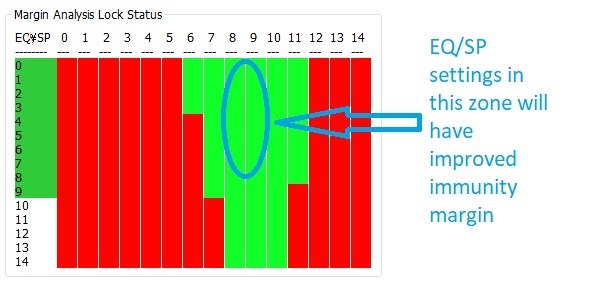
    –Use the ALP Margin Analysis tool to determine acceptable AEQ settings. Set AEQ/sFILTER min/max limits to allow only setting near the center of the “eye”.
    •Use the AEQ settings to increase the LOCK tolerance to errors (95x example).
    –Allow lock to establish with default AEQ settings
    –After Lock, Set 0xB9 to 0x3F. This increases the number of errors required for LOCK to drop. If this does not work, try the next three steps, one at a time.
    –Set 0x42(4) to 0x0. This stops parity errors from causing LOCK drop and is in line with how later parts operate.
    –Set 0x42(5) to 0x0. This stops packet encoding errors from causing LOCK drop.
    –Set 0x42(6) to 0x0. This stops FPD-Link Clock errors from causing LOCK drop.
    •We have seen immunity failures caused by power supply current limits. Check the voltage rails to make sure they stay in spec during the test. An optical probe is useful for this.
    •Try a common mode choke on the serial path if using STP/STQ. We use DLW21SZ900HQ2L.
    •Try adding a 10uF to 22uF ceramic cap from DC power to ground right at the DC connector.
    •Try a 2pF ceramic cap across the differential serial path near the AC blocking caps. If this works, check link margin to be sure it will work in the customers design.
    •Try a ferrite bead between cable shield and board ground. We have an experiment planned to quantify the effect.
    •Most of the time, you can get better BCI results without the EMC shield boxes.
    •Use EMC absorption sheets to narrow down where the vulnerable area is.
    •Use shielded connectors.
    Mike

  • Hi Mike,

    In our application, we are using a coax cable in our application.

    Is there a test report of immunity testing(BCI and radiated) available of the FPD-link III? Can you share the levels of these immunity tests?

    Is there an application note available to implement more robustness on the FPD-Link III via the DESER/SER registers(you were already mentioning the LOCK tolerance)?

    Thanks,
    Stijn

  • Hi Stijn,

    I've attached a report for a product that is different only in supported data rate.  It passes CISPR25 L5 and BCI at 200mA.  It was tested with Leone Dacar 462 coax. 

    I'm working on the app note now.  Here is the AEQ optimization content I have so far: 

    ---Use the ALP Margin Analysis tool to determine acceptable AEQ/SP settings.

    ---Set AEQ/sFILTER min/max limits to allow only setting near the center of the “eye”.

    Margin analysis user guide is here.

    Mike

    951_958_EMC_102255-5_Final.pdf

  • Looks like an image dropped from my last response.  Here it is:

  • Hi Mike,

    I have already measured the EQ/SP settings in the past and they were looking good(many green blocks, no issue here).
    I will look into the lock settings as well.
    Thank you for sharing the very detailed report, I and my team have some open questions about this;

    1. The EMC measurements are for DS90UB951-Q1/DS90UB958-Q1. Seem to be new components, no data online yet. Can we get the schematic/layout data for the EVM board used in the EMC tests? Are there any specific EMC design/layout guidelines for these new components, other than TI app notes we already got?
    2. The BCI test setup pictures clearly shows the EUT = EVM PCB (pg 169). For the other pictures (pg 155…) it’s not so clear what the EUT looks like. Is there any data available on the EUT used in this test. Eg is it an EVM in a shielded box? Details about the construction of the box?
    3. Is there a similar EMC report available for the existing 953/954, 935/954 or similar FDP-III SERDER combinations?

    Thanks,
    Stijn

  • Hi Stijn,

    1. I used the DS90UB953 and DS90UB954 EVMs to test it, which are online.  All 95x applications notes apply. 

    2. Both sides are TI EVMs.  Shield box is made by Bud Industries.

    3. This is representative of the 935/95x architecture.  Different line rates will have different spectral content. I've attached the 933/934 EMC report, but the 951/958 I already supplied is more representative of the 935/936 architecture.

    8726.933_934_CISPR25_BCI_121916.pdf

    Mike

  • Hi Mike,

    Thank you for sharing this information, this is appreciated.
    After reading your report, I still have an open question;

    In your test report of the DS90UB933, the test is performed with a BCI of 100mA.
    The test report you shared before(of the DS90UB951), this was done with 200mA.
    Can you please let me know what level is tested on the DS90UB935?

    Thanks in advance,

    Stijn

  • Hi Stijn,

    We only have the 935 topology tested at the higher 951 data rate.  Because immunity is less affected by data rate than emissions, we expect the 935 to pass BCI at 200mA assuming a well-designed PCB, shielded connectors, and a new Leone Dacar 462 or better cable.  Ideally we would have a report for each SERDES combination, but $10k multiplied by the full product matrix is not practical.  Therefore, we test one pair for each family that share topology and driver/receiver.

    Mike

  • Hi Mike,

    I looked to the pass/fail criteria of the EMC report, can you confirm you only look at the LOCK status?

    If I'm correct this doesn't say anything about errors introduced on the communication? Especially if you are keeping the LOCK status due to the register changes that you suggested(LOCK will be kept even if there are errors).

    Kind regards,

    Stijn

  • Hi Stijn,

    Yes, LOCK is the pass/fail criteria.  The standard has four possible results:

    1. LOCK is never dropped during the test
    2. LOCK is dropped but self-recovers
    3. LOCK is dropped and requires user intervention to recover.
    4. The product is damaged and cannot recover without rework

    Only the first result is considered a pass.

    I did some experimenting, and observed the BCI current that causes data errors to start is only a few mA below the level that causes LOCK to drop.

    Mike

  • Hi Stijn,

    Is further support needed?  If yes, I'm happy to continue to help.  If not, can you close this ticket?

    If you do close it and then later on have new questions, please feel free to open a new ticket.

    Best regards,

    Mike

  • Hi Stijn,

    Is any other help needed?  If not, please close this ticket.  If you have future questions, please open a new ticket.

    Best regards,

    Mike