This thread has been locked.

If you have a related question, please click the "Ask a related question" button in the top right corner. The newly created question will be automatically linked to this question.

TUSB212: Jitter

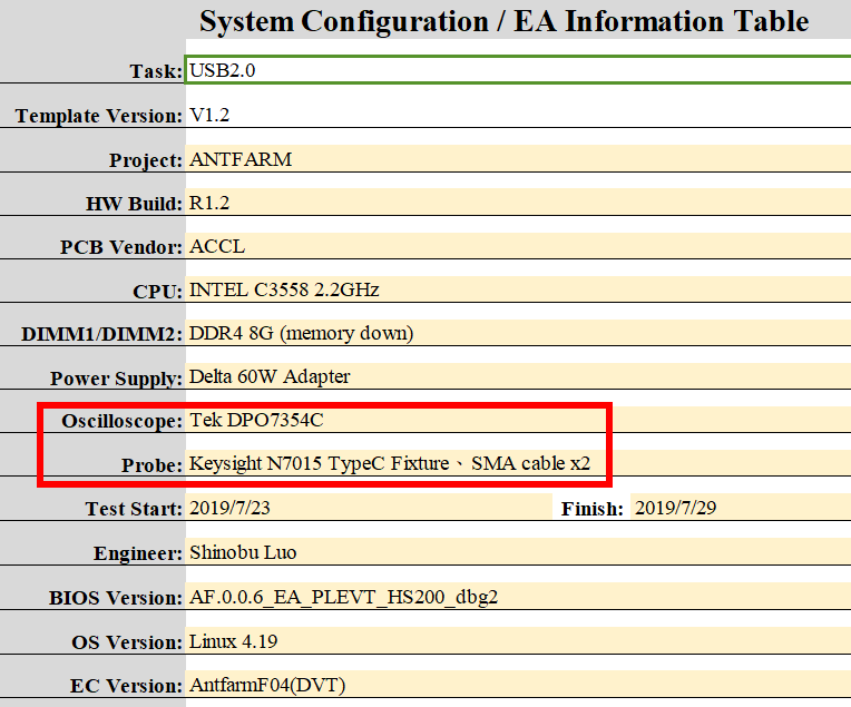
Part Number: TUSB212


Hi Sirs,

Sorry to bother you.

We've received the  DVT MB (with TUSB212).

Althoughi DVT MB pass the USB2.0 test, but the jitter is worse than EVT.

Is there any way to improve the jitter through TUSB212?

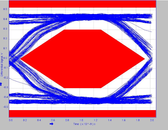
Here is the U2 margin pass eye diagram for you to reference.

For jitter issue, may we lower the AC boost level to lower the jitter?

Update-

We find change to high level of ac boost will let jitter be more obviously. If enhanced dc & ac boost level to max, can have more margin, but will also reduce V-swing tolerance.

Due to can't find any emphasis tuning option, do you have other ideas for this ?

Fig-1. DC boost = L ; AC boost = level 1  (default)

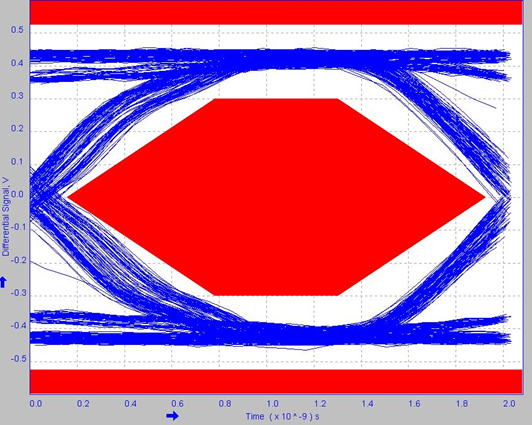
Fig-2. DC boost = L ; AC boost = level 3

Fig-3. DC boost = H ; AC boost = level 0

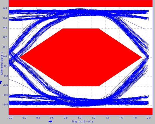
Fig-4. DC boost = H ; AC boost = level 3

Fig-5. DC boost = L ; AC boost = level 0 
(Wait for testing …)


  • Hi,

    Could you describe the application and what are the distances between USB host, TUSB212 and connector? Most of the eye diagrams (fig 2 - 4) posted exhibit large amounts of over equalization which can look like jitter but is not the same. In Fig-1 there does seem to be some jitter. Are you meeting the USB 2 jitter specification with your default settings? Is there a common mode choke in the USB 2 path? How does the eye look once this common mode choke is removed? 

  • Hi,

    Is there any more support needed for this issue? If so please reply with any relevant details so that I can further assist you. For now I will be marking this thread as "TI Thinks Resolved". If you have resolved your issue, please post the solution to the original problem/post for others with similar issues.

  • Hi Sirs,

    Thanks for your reply,

    update EA measurement result as below.

    From Fig.1, can see if set DC boost = LOW , AC boost = Level 0 , then the Jitter (?) will be more like the result of level 3 AC boost behavior, and still is margin on the left side of eye diagram.

    From Fig.2, can see if remove CMC on USB2.0 signals, it will fail and still is margin to TOP/BTN side.  (It can pass by retesting several times, but also can be fail during the process.)

    Could you please provide your comment for these ?  

    PS. Please refer to attached table as the Length of USB2.0 trace within Type-C port.

     USB2.0_TraceLength_20190726.xlsx

    Below is updating :

    1. By more testing,  if we set DC boost and AC boost to Level 0 , it has almost 50% chance to pass or fail.

    2. We keep try another setting of DC / AC boost Level , find if set them both to Max level , then the eye diagram can keep PASS, but still have margin risk to overshoot / undershoot spec.

    Do you have any idea for this ? Please inform us.


    Thanks a lot.


    DC boost / AC boost = Level MAX, with CMC

  • Hi,

    Before I provide more comments please give some additional details regarding the application and test setup? 

  • Hi Sirs,

    The application is Storage Brick , and please refer to below table as test setup information and model names of Scope and probe.

              If there's any question, please inform me.  Thanks ~

  • Hi Sirs,

    Sorry for pushed, any update on here?

    Thanks!!

  • Hi Sirs,

    Sorry for pushed, any update on here?

  • Hi,

    Can you try DC boost / AC boost = Level MAX, without CMC? If the results is not improved then I believe  the coax cable may also be introducing additional inductance on the USB 2.0 data lines causing the issue with the eye test? Is it possible to measure before and after the coax cable? Could you provide the DP and DM waveform of these cases?