Part Number: TPS65982
Hi, team
I used the TPS65982 EVM module to validate the OCP functions of TPS65982. I measured the OCP threshold
under various Maximum Current and Peak Current setting. And below is the test results.
I have some questions about the test result.
1. Is my test results correct?
2. If the test result is correct, so can we get the followings :
- When TPS65982 GUI tool sets TPS65983 or TPS65982 peak current as 100%, actual peak current set is 100%.
- When TPS65982 GUI tool sets TPS65983 or TPS65982 peak current as 130%, actual peak current set is 150%.
- When TPS65982 GUI tool sets TPS65983 or TPS65982 peak current as 150% or 200%, actual peak current set is 200%.
TI TPS65982 EVM Measured OCP thresholds under various Maximum Current and Peak Current settings.
|
Maximum current Setting (A) |
Peak current setting |
Source 5V from Internal Switch OCP (A) |
Source 5V from external Switch OCP(A) |
Source 9V from external Switch OCP(A) |
Source 12V from external Switch OCP(A) |
Source 15V from external Switch OCP(A) |
Source 20V from external Switch OCP(A) |
|
0.5 |
100% |
1.09 |
1.92 |
1.93 |
1.94 |
1,96 |
1.98 |
|
130% |
1.09 |
1.92 |
1.93 |
1.94 |
1,96 |
1.98 |
|
|
150% |
1.23 |
1.92 |
1.93 |
1.94 |
1,96 |
1.98 |
|
|
200% |
1.23 |
1.92 |
1.93 |
1.94 |
1,96 |
1.98 |
|
|
1 |
100% |
1.23 |
1.92 |
1.93 |
1.94 |
1,96 |
1.98 |
|
130% |
1.75 |
1.92 |
1.93 |
1.94 |
1,96 |
1.98 |
|
|
150% |
2.28 |
2.49 |
2.49 |
2.51 |
2.54 |
2.57 |
|
|
200% |
2.28 |
2.49 |
2.49 |
2.51 |
2.54 |
2.57 |
|
|
1.5 |
100% |
1.75 |
1.92 |
1.93 |
1.94 |
1,96 |
1.98 |
|
130% |
2.52 |
2.49 |
2.49 |
2.51 |
2.54 |
2.57 |
|
|
150% |
3.34 |
3.61 |
3.62 |
3.65 |
3.69 |
3.74 |
|
|
200% |
3.34 |
3.61 |
3.62 |
3.65 |
3.69 |
3.74 |
|
|
2 |
100% |
2.28 |
2.49 |
2.5 |
2.52 |
2.54 |
2.57 |
|
130% |
3.34 |
3.61 |
3.62 |
3.65 |
3.69 |
3.74 |
|
|
150% |
3.34 |
4.73 |
4.74 |
4.79 |
4.84 |
4.91 |
|
|
200% |
3.34 |
4.73 |
4.74 |
4.79 |
4.84 |
4.91 |
|
|
2.5 |
100% |
2.78 |
3.04 |
3.05 |
3.08 |
3.1 |
3.14 |
|
130% |
3.34 |
4.16 |
4.17 |
4.21 |
4.25 |
4.31 |
|
|
150% |
3.34 |
5.85 |
5.87 |
5.92 |
5.99 |
6.07 |
|
|
200% |
3.34 |
5.85 |
5.87 |
5.92 |
5.99 |
6.07 |
|
|
3 |
100% |
3.34 |
3.61 |
3.62 |
3.65 |
3.69 |
3.72 |
|
130% |
3.34 |
5.28 |
5.3 |
5.35 |
5.4 |
5.48 |
|
|
150% |
3.34 |
6.95 |
6.98 |
7.04 |
7.11 |
7.22 |
|
|
200% |
3.34 |
6.95 |
6.98 |
7.04 |
7.11 |
7.22 |
|
|
4 |
100% |
3.34 |
3.61 |
3.62 |
3.65 |
3.69 |
3.72 |
|
130% |
3.34 |
5.28 |
5.3 |
5.35 |
5.4 |
5.48 |
|
|
150% |
3.34 |
6.95 |
6.98 |
7.04 |
7.11 |
7.22 |
|
|
200% |
3.34 |
6.95 |
6.98 |
7.04 |
7.11 |
7.22 |
|
|
5 |
100% |
3.34 |
3.61 |
3.62 |
3.65 |
3.69 |
3.72 |
|
130% |
3.34 |
5.28 |
5.3 |
5.35 |
5.4 |
5.48 |
|
|
150% |
3.34 |
6.95 |
6.98 |
7.04 |
7.11 |
7.22 |
|
|
200% |
3.34 |
6.95 |
6.98 |
7.04 |
7.11 |
7.22 |
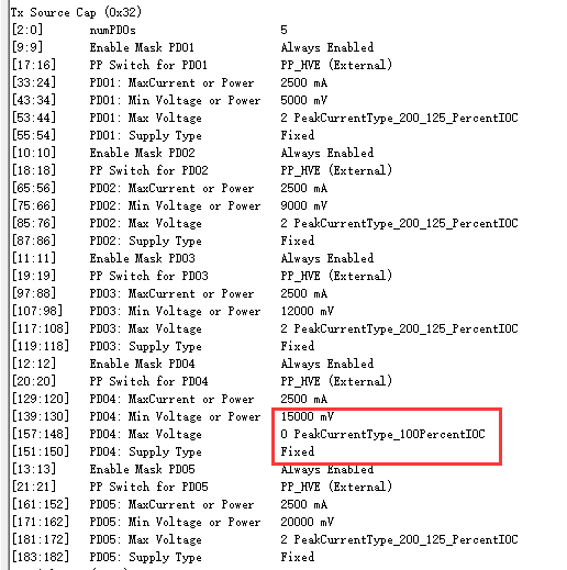
3. Figure below shows the 0x32 register of TPS65982, 15V PDO Peak current always keep at 100% and can’t change by the firmware configure tool.
Is there any bugs about this?