Hi
If I use SN65HVS885.
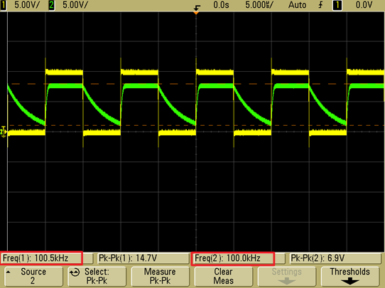
IF IPx have a 100K~200KHz PWM.
Can I get same frequence PWM on REx?
Shawn
Original question:

Hi
If I use SN65HVS885.
IF IPx have a 100K~200KHz PWM.
Can I get same frequence PWM on REx?
Shawn