This thread has been locked.
If you have a related question, please click the "Ask a related question" button in the top right corner. The newly created question will be automatically linked to this question.
Dear team,
Customer has some questions when using DS110DF111. Would you kindly give some suggestion?
1. How to look at the result of eye monitor? Through I2C?
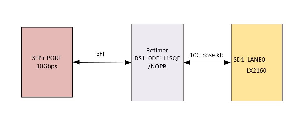
2. The application situation is NXP MCU--XFI<-->Retimer<-->SFI--SFP+. Is it OK?
3. When DS110DF111 connect with SFP+, there is still coupling capacitor inside SFP module, will the IC need to add coupling capacitor again? The design guide of this IC have added the capacitor.
Thanks.
Sammi
Hi, my inputs below.
Plotting an Eye Diagram
The Eye Opening Monitor is capable of plotting an equalized, but non-retimed eye to represent the quality of signal that is going into the CDR block. This feature is useful for diagnosing gross signal integrity errors. The eye plot generated by the EOM cannot be used to extrapolate performance to bit error rates beyond 1e-7.
The EOM generates the eye plot according to a 64 x 64 matrix. Each grid space in the matrix consists of a 16-bit word that represents the number of times the incoming data stream touches that particular phase and voltage level. The EOM under-samples the incoming data stream by recording the total hit count for each combination of phase and voltage, one grid space at a time.
To configure the EOM to plot the eye diagram, sometimes called fast eye capture, use the following registers.
Step |
Register[bits] |
Value |
Description |
1 |
0x3E[7] |
0 |
Disable lock EOM lock monitoring |
2 |
0x2C[6] 0x11[7:6] |
0 2’b xx |
Set the desired EOM vertical range as 2’b xx |
3 |
0x11[5] |
0 |
Power on the EOM |
4 |
0x24[7] |
1 |
Enable fast EOM |
5 |
0x24[0] 0x25 0x26 |
1 |
When 24[0] is 1 begin read out of the 64 x 64 array, discard first 4 bytes |
6 |
0x24[0] 0x25 0x26 |
1 |
Continue reading information until the 64 x 64 array is complete. |
7 |
0x3E[7] 0x2C[6] 0x11[5] 0x24[7] |
1 1 1 0 |
Return the EOM to its original state. Undo steps 1-4 |
The data recorded from the Eye Opening Monitor (EOM) begins at (X, Y) position (0, 0) and proceeds to position (0, 63). Next, the Y-value is reset to 0 and the X-value is incremented. This process is repeated until the entire 64 x 64 matrix is read out.
Hi,
Yes, TI has a software GUI that enables the user to plot the retimer input eye diagram. See below.
Cordially,
Rodrigo Natal
HSSC Applications Engineer
Hi
How much loss can be supported on DS110DF111 XFI/SFI signal of input channels ?
How much loss can be supported on DS110DF111 XFI/SFI signal of output channels ?
songlin ren
thanks
Hi,
Cordially,
Rodrigo Natal
HSSC Applications Engineer
Hi ,
Regarding the SW tool , post installing the software in PC do we need to have adaptor (usb to i2c) to connect to the i2c bus ? In my design, i have below connection NXP - retimer - SFP+ and have i2c connection. I would like to use the software tool to plot the eye by capturing data from the board. Can you please advice here
--
Krish
Hi,
In order to use the current TI SigCon Architect software GUI you need a TI USB2ANY adapter to interface to the retimer via I2C. See link below for product and order info:
http://www.ti.com/tool/USB2ANY
You may reference the TI retimer EVM user's guide per link below.
http://www.ti.com/lit/ug/snlu142a/snlu142a.pdf
Cordially,
Rodrigo Natal
Hi,
The DS110DF111 indeed supports this application case. There is no KR or SFI specific settings that would need to be applied to the retimer. The user would simply need to the set the retimer for 10.3125Gbps CDR rate. Additionally, I would recommend to use adapt mode 2 (i.e. DFE enabled.)
Regards,
Rodrigo Natal
HSSC Applications Engineer