This thread has been locked.

If you have a related question, please click the "Ask a related question" button in the top right corner. The newly created question will be automatically linked to this question.

TCA6424A: Please help check if the schematic of TCA6424ARGJR is correct

Part Number: TCA6424A
Other Parts Discussed in Thread: TPD4E1U06

Hi

Because there is a problem at present, four white screens are displayed in the test (non-static test), three of which are always present, and the other is restored after a period of time;

The three machine are displayed white screens, which through log analysis, shows that the GPIO chip is abnormal, and one of the machines displays normal after replacing the new material;
Please help check if the schematic of TCA6424ARGJR is correct, PIN31 is 1.8V power supply, PIN27 is 5V power supply, and will reply as soon as possible.
The following is the relevant schematic:

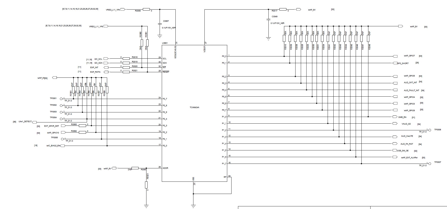
GPIO Expend Interface part:


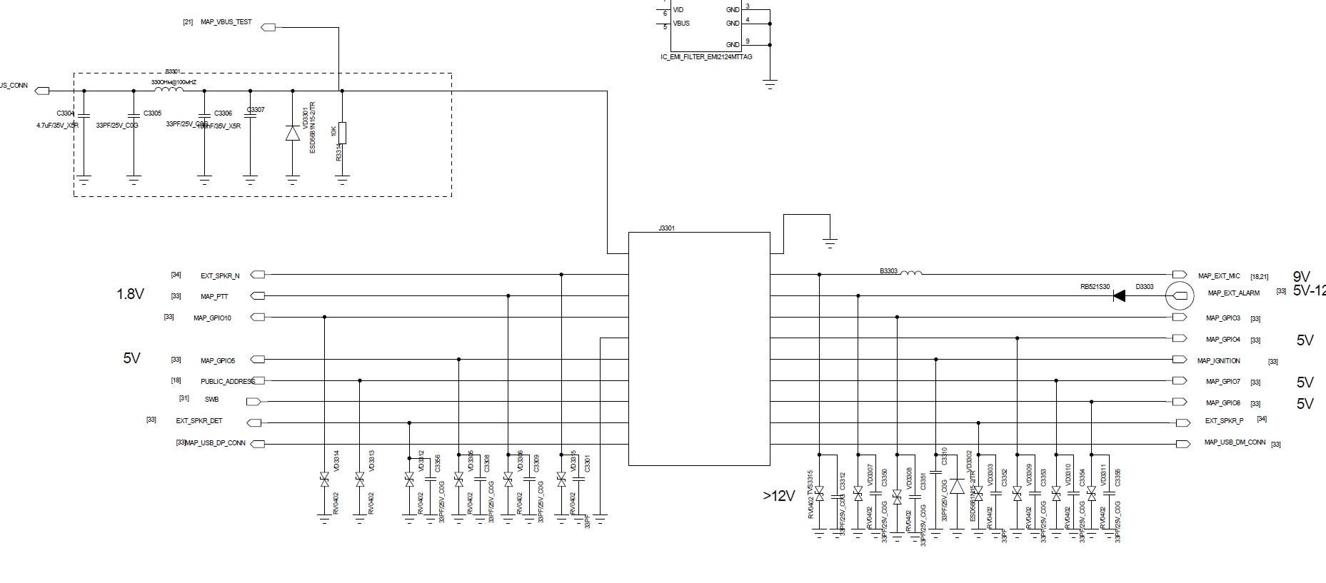
If our demand is the interface of GPIO Expend IC (TCA6424ARGJR) connection, the electrostatic voltage level that can be achieved is 15KV in air and 8KV in contact. The maximum electrostatic voltage of TCA6424ARGJR is 2KV, right? Is there a more suitable recommendation?

It's an urgent case.

Thanks a lot.

Best Regards

Elsa Duan

  • Hey Elsa,

    In terms of the TCA6424A schematic, I don't see anything wrong. Our device does require any inputs to be referenced (such as unused GPIOs to be tied to GND or up to VCC with a pull up resistor) but leaving them floating would just cause INTs to trigger due to the inputs potentially floating to different logic levels and a bit more consumption current. I mention this because I do see some DNP resistors.

    Were you able to confirm if the TCA6424A previously was damaged? You mention that ESD levels and our device is only rated for 2kV so anything above that could potentially break our device. If this is what you suspect damaged the device, you may want to add external ESD protection on the pins you may expect ESD events may occur on. If you would like, I can pin this thread to someone in our ESD team to provide a recommendation for this.

    Thanks,

    -Bobby

  • Hi Bobby,

    ESD protection devices can be recommended, we require contact discharge 8kv, air discharge 15kv;

    The test found three white screen problems displayed.
    1. In the AFM test, a white screen problem was found after high and low temperature test, confirming that the GPIO chip was damaged.
    2. Audio test, 2 machines white screen, confirm the cause of GPIO chip damage, one of the machines returned to normal after replacing the GPIO chip

    If there is no problem with the schematic, what is the problem, will it be the impact of the DNP Resistors you mentioned?

    Software part:
    The software code did not find an exception, and the chip does not have the concept of initialization or no initialization. There is no initialization process itself. There is only one hard reset pin, and it is enabled after power-on. Only the concept of input and output is the default. Input; some are configured as outputs by individual applications or drivers, and some are configured as inputs. Is that right?

    Now the problem caused by the damage of the GPIO chip, how to solve it, is it only possible to do the bad chip analysis of the damaged chip?


    Thanks a lot


    Best Regards

    Elsa Duan

  • user5707026 said:

    ESD protection devices can be recommended, we require contact discharge 8kv, air discharge 15kv;

    I will retag this thread so that someone from our ESD team may be able to suggest a possible product.

    If there is no problem with the schematic, what is the problem, will it be the impact of the DNP Resistors you mentioned?

    I think this would be unlikely, the worst I can imagine would be larger 'leakage current' resulting in more consumption current through Vcc.

    Software part:
    The software code did not find an exception, and the chip does not have the concept of initialization or no initialization. There is no initialization process itself. There is only one hard reset pin, and it is enabled after power-on. Only the concept of input and output is the default. Input; some are configured as outputs by individual applications or drivers, and some are configured as inputs. Is that right?

    Our device starts off as all inputs. You would need to communicate through I2C to set internal registers to set the pins to be outputs. Some can be inputs and some can be outputs at the same time (example p01-P07 = output LOW and P00 input). Or all can be outputs (or all could be inputs). It just depends how you set up the registers after powering up the device. If left alone, they will just be inputs until configured otherwise.

    Now the problem caused by the damage of the GPIO chip, how to solve it, is it only possible to do the bad chip analysis of the damaged chip?

    We could do some testing on the damaged device by doing continuity testing/ curve traces. We would need to contact a quality engineer on our side to get something like this in the system though. After those tests are done, I may be able to put the device on the bench to see what kind of behavior I see (to see if the pin is damaged in a functional perspective) assuming the quality engineer thinks this is necessary.

     ^^If this is what you would like to do, please contact me at duynguyen@ti.com so I can set you up with a quality engineer

    -Bobby

  • Hi Boddy

    Thanks a lot for your advice.

    1. Whether I need to release a new question about ESD for TCS6424A?

    2. We may want to do FA, If I create a product return request, can you help me push the local pass it?

    If it is ture, I will sent the Submit PDF for you.

    Thanks

  • "1. Whether I need to release a new question about ESD for TCS6424A?"

    I've reassigned the question to our ESD team for a suggested device for you.

    "2. We may want to do FA, If I create a product return request, can you help me push the local pass it?"

    I would be able to pass your request to our quality engineer who can provide further support for you.

    -Bobby

  • Hi Elsa,

    Based on reading the above thread, I'll jump in and recommend an ESD solution. Please take a look at the TPD4E1U06 (http://www.ti.com/product/TPD4E1U06 which I believe will meet you requirements or you may review our portfolio on TI.com/ESD for more options

    Regards,

    Obi Oji