This thread has been locked.

If you have a related question, please click the "Ask a related question" button in the top right corner. The newly created question will be automatically linked to this question.

TUSB8041: Schematic Review

Part Number: TUSB8041


Hi, 

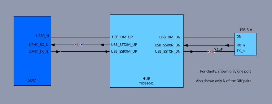
I have a Nvidia SOM, which is connected through TUSB8041 to 3 x USB 3 ports.

Diagram and schematic are attached.

 /cfs-file/__key/communityserver-discussions-components-files/138/ktigs_2D00_usb_5F00_V1-v06-8_2D00_sep_2D00_19.pdf


My debug so-far found the following:

  1. There are FAQs that I missed....
    https://e2e.ti.com/support/interface/f/138/t/719918?-FAQ-How-do-I-debug-a-TI-USB-Hubs-when-downstream-ports-are-non-operational-
    http://www.ti.com/jp/lit/an/slla314/slla314.pdf   (USB 1.1/2.x, but seems still relevant)

  2. There's 5V, 3.3v and 1.1v on the board.
  3. I can't see any clock at the crystal pins (actually on the optional resistor).  Plan to place 1M resistor and re-test.
  4. Found that missed a pull-up on the RESET input.  Plan to pull to 3.3v through 8.2K.
  5. Seems to me that I've swapped SSTX/RX.  Plan to swap it on the 0R pads.
  6. Seems that I haven't placed capacitors on SSTX of DN ports.  Plan to replace 0R with 0.1uF
  7. Seems that I've placed capacitors on USB_Dx_DN by mistake.  Plan to replace to 22R.

Any suggestion on debug of the crystal?  
Can you please review and inform on any other issue I got with the design.

Thanks in advance,

Ishay

  • Hi Ishay,

    I would review this document in addition and come back with any questions or issue on the schematic. I also recommend using TUSB8041A instead of TUSB8041. For the Crystal issue, I wold verify that your VDD and VDD33 are at the appropriate levels and that a clean reset occurs. Start with a passive reset by populating a 0.1 uF capacitor and disable active reset device for now (TPS3808G01DBVR). 

    • You are also missing AC coupling cap on the SSTX upstream port.
    • Optional but recommended for new designs. SSTX should be AC coupled with 220 nF and SSRX should be AC coupled with 330 nF.
    • Schematic checklist:  
  • Thanks Malik for your prompt reply, providing the TUSB8041 FAQ, and for reviewing the schematics.

    I've added to our pending-issues document, to replace with TUSB8041A.

    I've found that I missed the 1M on the crystal pins.

    I've measured 1.107v and 3.165v.  Plan to fine-tune the 3.3v in next assembly.  

    I plan to raise pin#1 of the TPS3808G01DBVR, and assemble 0.1uF (C23).  Which is better - 1uF or 0.1uF? (FAQ specifies 1uF.)

    Attached is the updated diagram, I hope that now it's correct.

    (Note that I assume that with the TUSB8041, there's no need for series resistors of 22-33, as specified for older hubs.)

    BR, Ishay

  • Hi Ishay,

    I recommend 1 uF as it provides a longer reset more inside the limits specified in the datasheet at power up. Then image posted is correct. In the next build I recommend starting bring-up/debug by ensuring the power-on reset sequence is correct and then work to see if devices connect to the SOM.