This thread has been locked.

If you have a related question, please click the "Ask a related question" button in the top right corner. The newly created question will be automatically linked to this question.

DP83822I: DP83822i config issue

Part Number: DP83822I

Hi:

   we use 83822 in one project ,we config the 83822 as RGMII mode , our original hardware works well, but we relayout  for some reasons  , dp83822 can not enter RGMII mode though there have no any configuration change . it seems 83822 enter the RMII mode .the RX_clk have no any clock . below is the details .

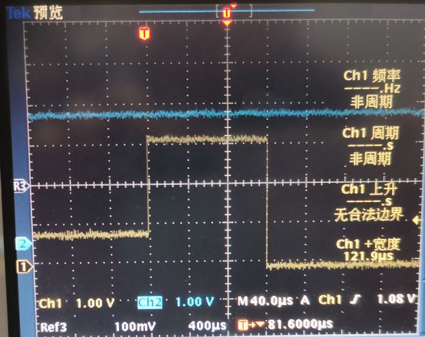
        RX_ER config as mode 3, means 6.2K up to VCC ,and 1.96K down to GND . also measure RX_ER have a 200ms voltage pulse during power on .

        when we read the 0x0467, original hardware is 0900, relayout PCB is 0A08 seems all config as RGMII .

        when we read the 0x0017, original hardware is 0249, relayout PCB is 0065 seems  original one enter  RGMII .but the relayout one not enter RMII, which enter RMII.

       it is really confuse me .!!!

       why bootstrap seems ok ,but the IC not work as normal, would you pls give me some hint .

       also if we want to config 0x0017 as RGMII permanently through  USB 2 MDIO tools , what is the step? we had try config 001F , seem not ok .

    hope get answer quickly .

   thank you very much


  • Hello,

    Can you please tell me more about what the changes on the board were?

    There must be something effecting the PHY. What VDDIO are you using?

    Can you measure voltage at power on? Does the voltage on RX_ER meet the requirement for voltage level shown for MODE 3 in "Table 10. 4-Level Strap Voltage Ratios"?

    Thanks,

    Vibhu

  • Hi:

        sir ,thank you quick answer . I will measure the VDDIO voltage to see any changes .

        one more question , if I can USB2 MDIO software fix the RGMII mode for register 0x0017, if yes , would you pls teach me how to do ?

        thank you very much

  • Hi:

         today, I measure the RX_ER pin power on voltage , got a strange curve .pls see below , Ch1 is RX_ER signal , Ch2  is VDDIO , the RX_ER  signal first enter the latch voltage about 0.8V for about 200ms when power on , but at last of latch in, there have a about 120us VDDIO voltage(3.3V),I do not know what happened , if final latch voltage is 3.3V , but not 0.8V ,

         also , my last question is how to use  USB 2 MDIO config the RX_ER to mode 3 permanently .

  • sorry for the curve

  • Hi:

        sir , any update ? why the RX_ER have about 120us jump to 3.3V , dP83822 still enter RMII mode .  

  • Hello,

    Sorry for the late response, I am a bit confused:

    "when we read the 0x0017, original hardware is 0249, relayout PCB is 0065 seems  original one enter  RGMII .but the relayout one not enter RMII, which enter RMII."

    You want this PHY to function in RGMII mode correct?

    To enter RGMII mode RX_ER pin must have a voltage that sets it to MODE 2 or 3 to enable RGMII. You are using MODE3.

    Is there any other device on the board driving the RX_ER pin. Is this connected anywhere in the system apart from the voltage divider to set it into mode 3?

    To configure RGMII via registers set RCSR (0x0017) bit 9 to 1. (see "Table 37. 0x0017 RMII and Status Register (RCSR)" in datasheet)

    If your intention is also to set to auto MDIX, please also set PHYCR (0x0019) bit 15 to 1. (see "Table 39. 0x0019 PHY Control Register (PHYCR)" in datasheet)

    Thanks,

    Vibhu