Part Number: DS90UB953-Q1
Hi team,
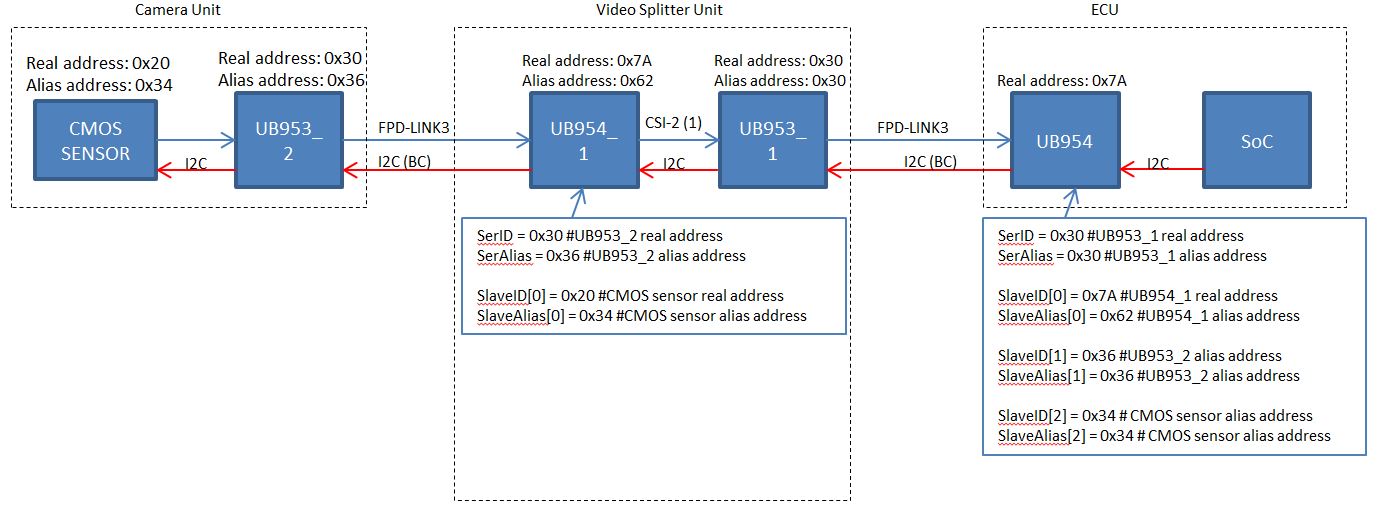
•Isn’t it possible for SoC in ECU unit to control CMOS Sensor in Camera Unit over additional UB953/954 in video splitter unit?
•If yes, could you advise how to assign addresses?
Please see attached system configuration and advise if this is possible or not?
regards,