Other Parts Discussed in Thread: TCAN4550EVM, TCAN4550
Hi,
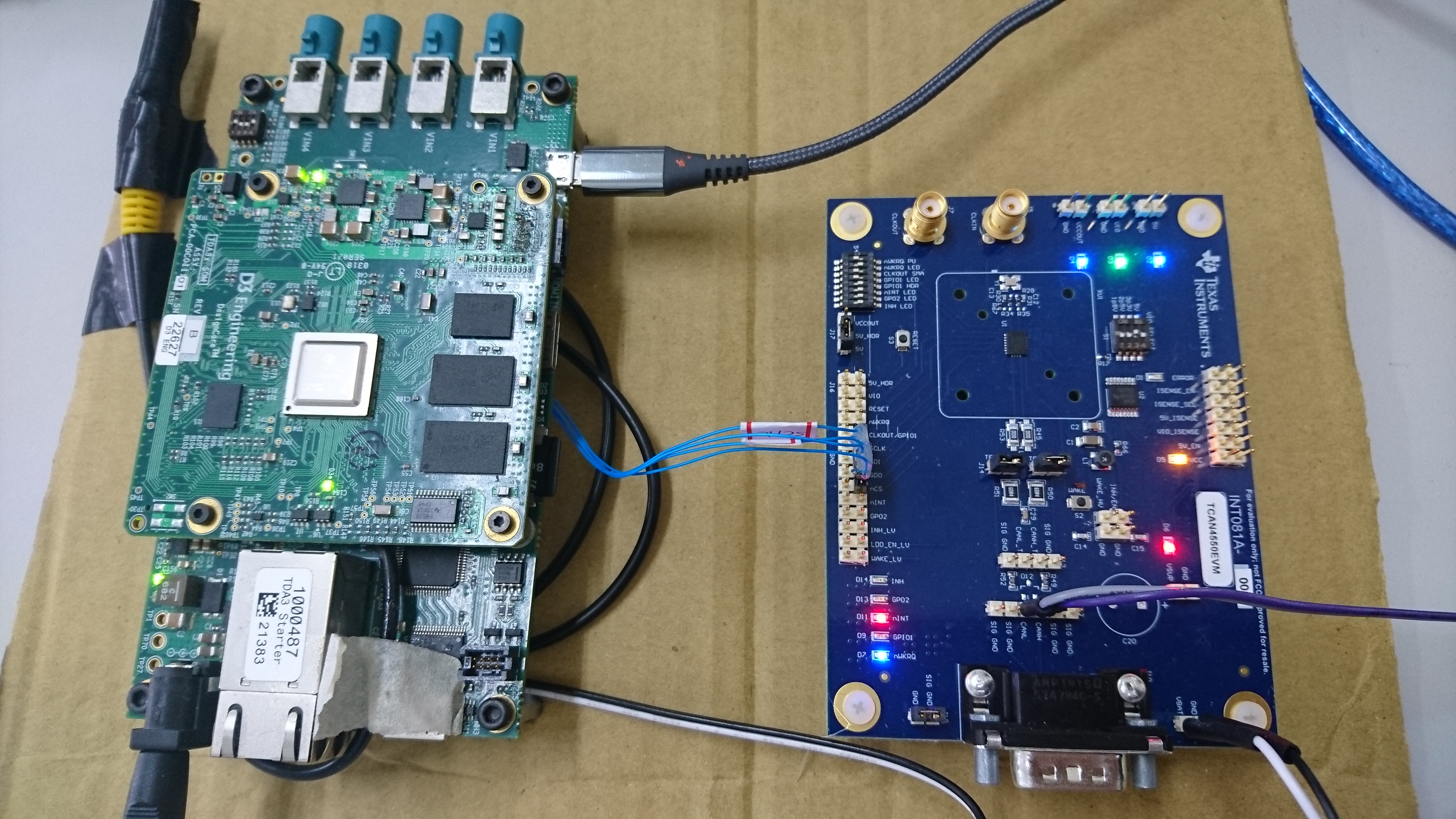
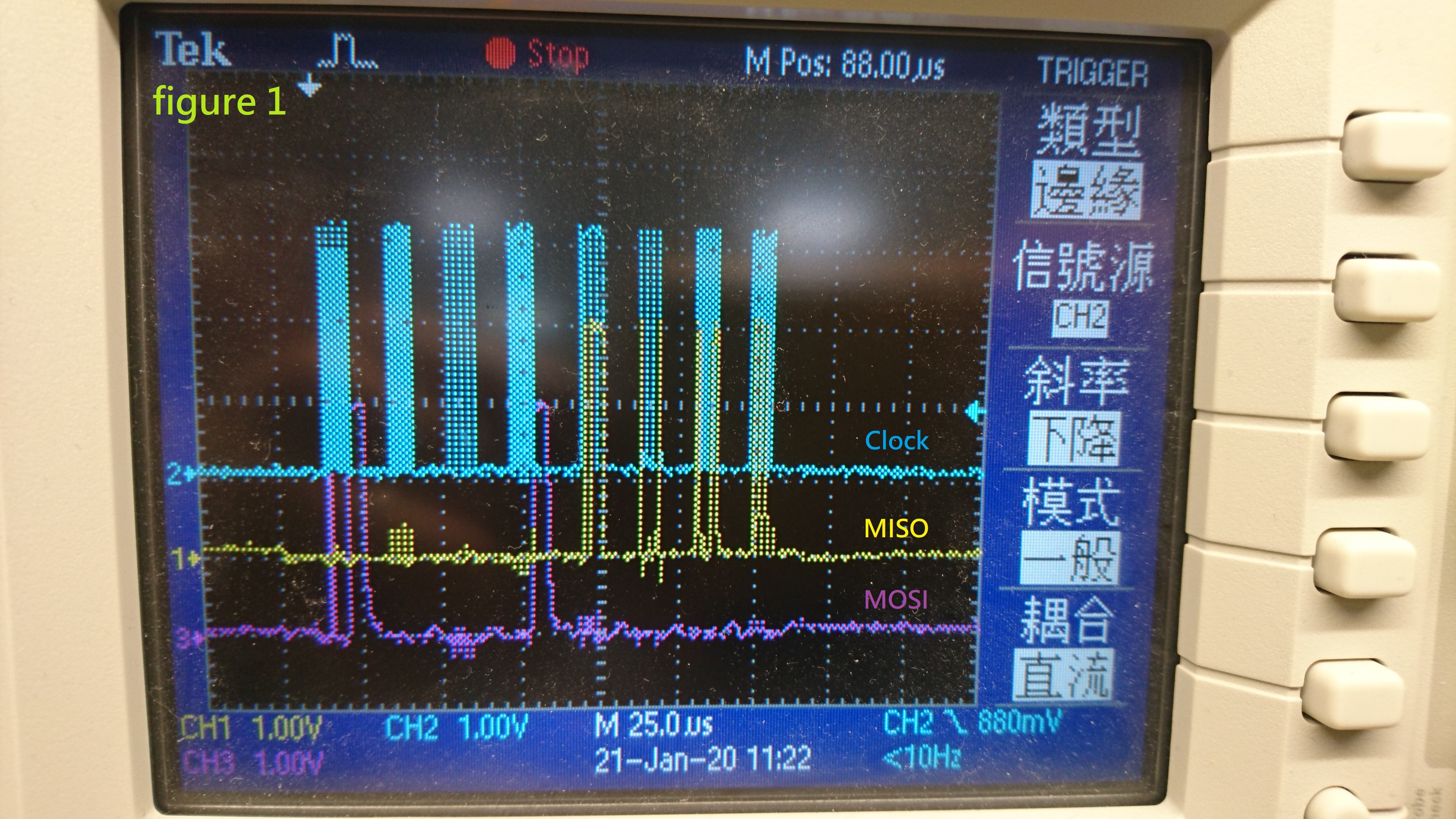
I have used vsdk3.7 and TI provided functions(in utils_mcspi.c) to do SPI communication test.
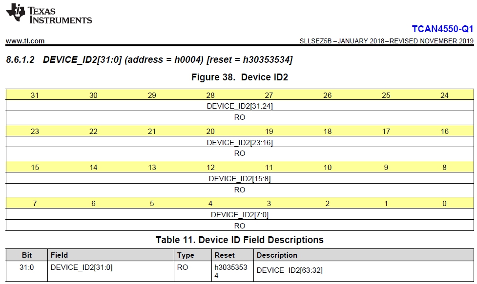
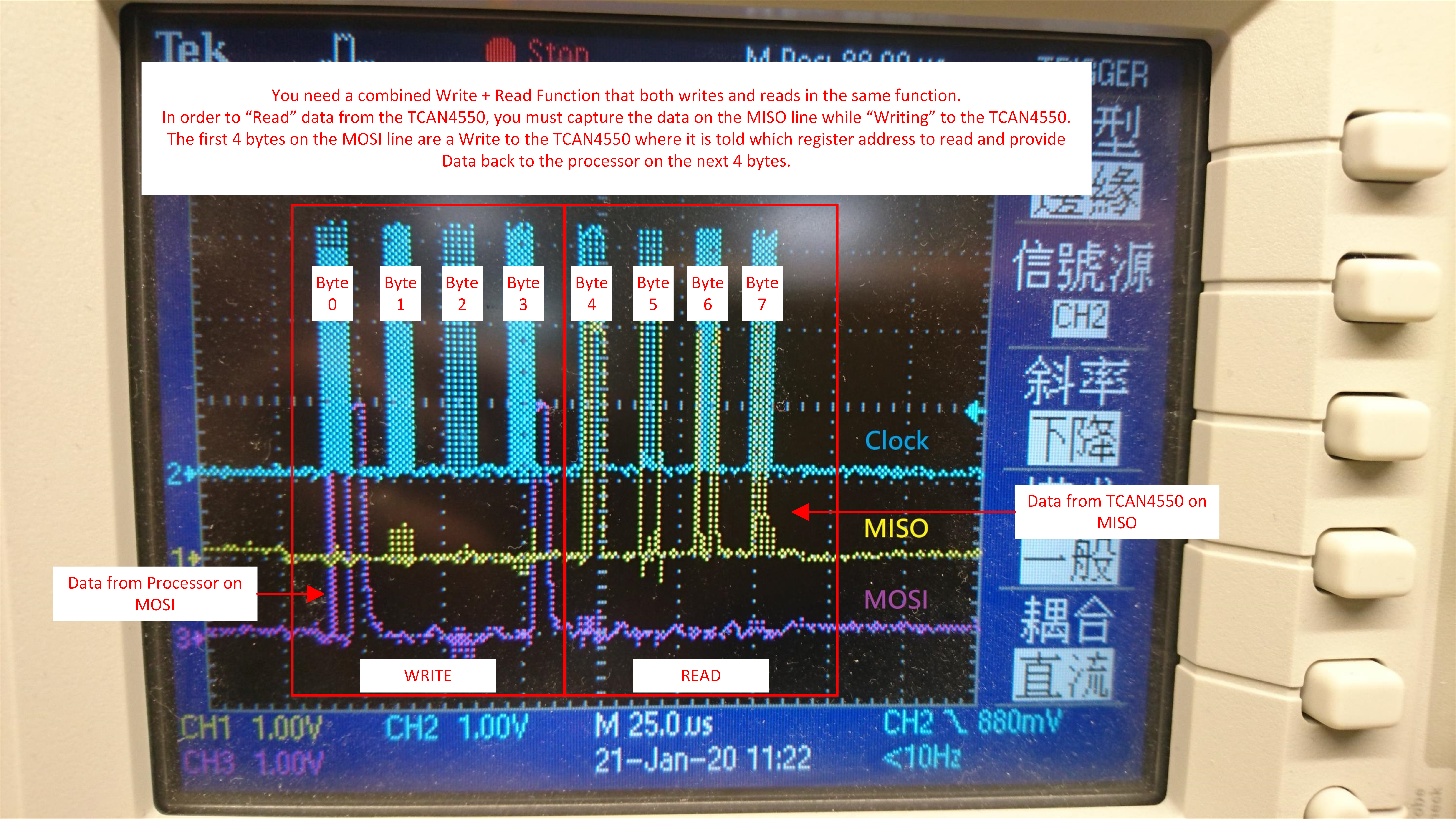
I have read TCAN4550 datasheet, TCAN45xx software user's guide, and followed SPI Read or Write format to send a message to TCAN4550EVM.
However, D3-TDA3xx-rvp seems can't get the right response from TCAN4550EVM.
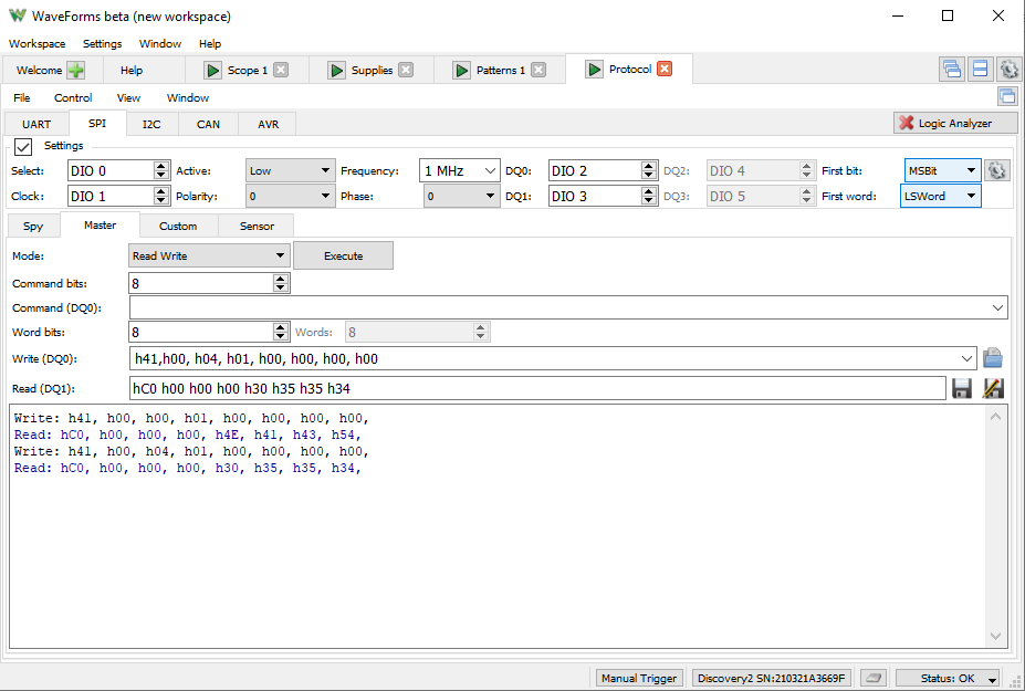
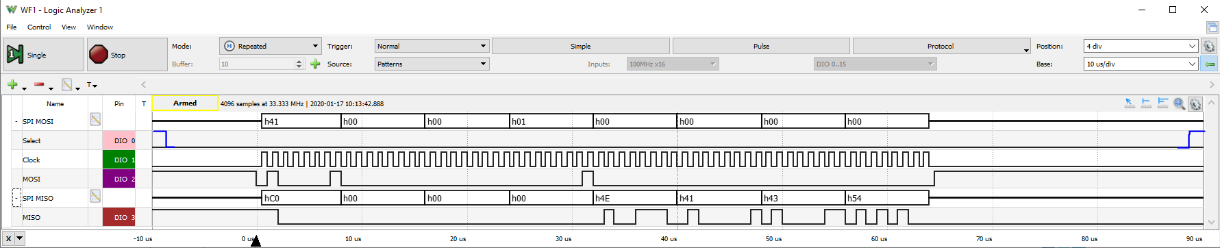
Please tell me what messages I should send/receive to prove SPI communication is successful.
My code shows below.
Could you help me check hardware configuration and fix related software problems?Thank you.
Regards,
Ethan
void spi_main()
{
UInt32 mcSpiInstNum=1U; // 0U, 1U, 2U, 3U
EDMA3_DRV_Handle edmaHandle;
void *gSpiHandle;
UInt8 i, j;
UInt8 dataRx[16], dataTx[16];
UInt32 dataLengthTx, dataLengthRx;
UInt32 val;
val = HW_RD_REG32(SOC_L4PER_CM_CORE_BASE + CM_L4PER_MCSPI2_CLKCTRL);
Task_sleep(1000U);
AppUtils_setBoardMux();
Utils_mcspiInit(mcSpiInstNum);
Task_sleep(500);
edmaHandle = Utils_dmaGetEdma3Hndl(0U);
Task_sleep(500);
gSpiHandle = Utils_mcspiOpen( (UInt8)mcSpiInstNum, (UInt8)mcSpiInstNum , 0, edmaHandle);
Task_sleep(1000);
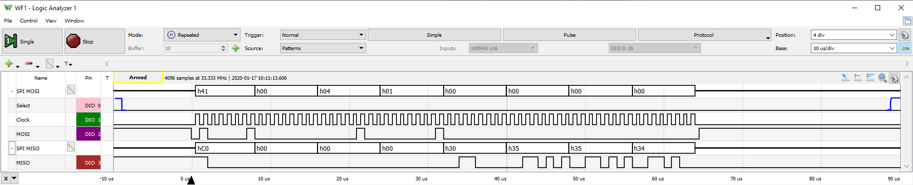
memset(dataTx, test, sizeof(dataTx));
dataTx[0] = 0x41;
dataTx[1] = 0x00;
dataTx[2] = 0x04;
dataTx[3] = 0x01;
dataTx[4] = 0x00;
dataTx[5] = 0x00;
dataTx[6] = 0x00;
dataTx[7] = 0x00;
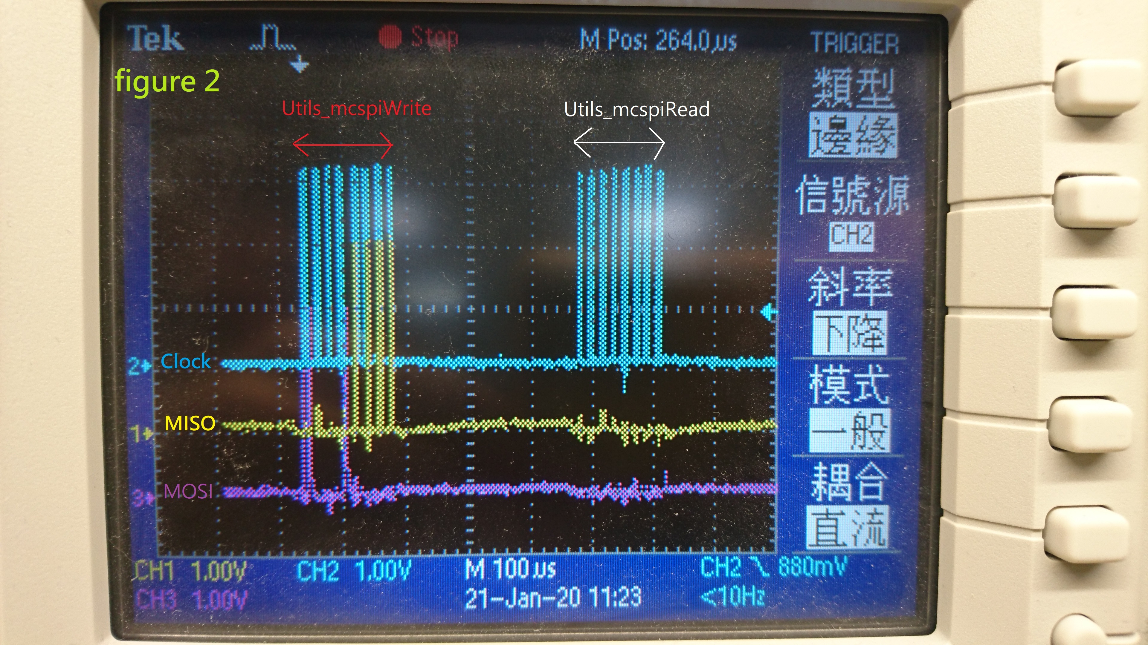
dataLengthTx = Utils_mcspiWrite(gSpiHandle, dataTx, 8U);
Vps_printf("dataTx[0] = %02X, dataTx[1] = %02X, dataTx[2] = %02X, dataTx[3] = %02X \n", dataTx[0], dataTx[1], dataTx[2], dataTx[3]);
Vps_printf("dataTx[4] = %02X, dataTx[5] = %02X, dataTx[6] = %02X, dataTx[7] = %02X \n", dataTx[4], dataTx[5], dataTx[6], dataTx[7]);
Task_sleep(500);
memset(dataRx, 0x00, sizeof(dataRx));
dataLengthRx = Utils_mcspiRead(gSpiHandle, dataRx, 8U);
Vps_printf("(A)dataRx[0] = %02X, dataRx[1] = %02X, dataRx[2] = %02X, dataRx[3] = %02X \n", dataRx[0], dataRx[1], dataRx[2], dataRx[3]);
Vps_printf("(A)dataRx[4] = %02X, dataRx[5] = %02X, dataRx[6] = %02X, dataRx[7] = %02X \n", dataRx[4], dataRx[5], dataRx[6], dataRx[7]);
Utils_mcspiClose(gSpiHandle);
Utils_mcspiDeinit(mcSpiInstNum);
}