This thread has been locked.

If you have a related question, please click the "Ask a related question" button in the top right corner. The newly created question will be automatically linked to this question.

TPS65983B: Issue on ATX FW feature

Part Number: TPS65983B

Our product is designed based on the Thunderbolt Intel Reference Design of APEX CREEK ATX. And we’re supporting the ATX firmware functionality (based on Intel reference).

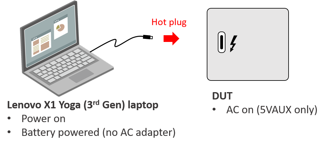
We are currently observing an outlier behaviour when a Lenovo X1 Yoga (3rd gen) is hot-plugged into our product when running from AUX power.

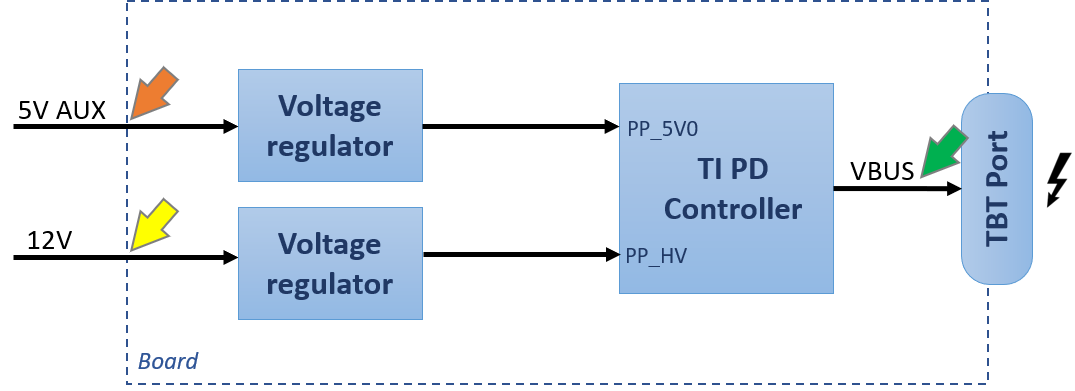
When a Lenovo X1 Yoga Laptop is hot-plugged to our product, there is a huge current pulse (3A) being drawn from the Lenovo laptop from AUX power. This behavior is different compare to what we see from a hot plug to MacBook or Dell Latitude Laptop. Additionally, we’re expecting that the TI TPS65983B should switch to the main power rails (since we’re using the ATX firmware) so that the current would be drawn from the main power instead of drawing from the AUX power rail. 


 Below are the probe point & scope shot that we have with Lenovo.  

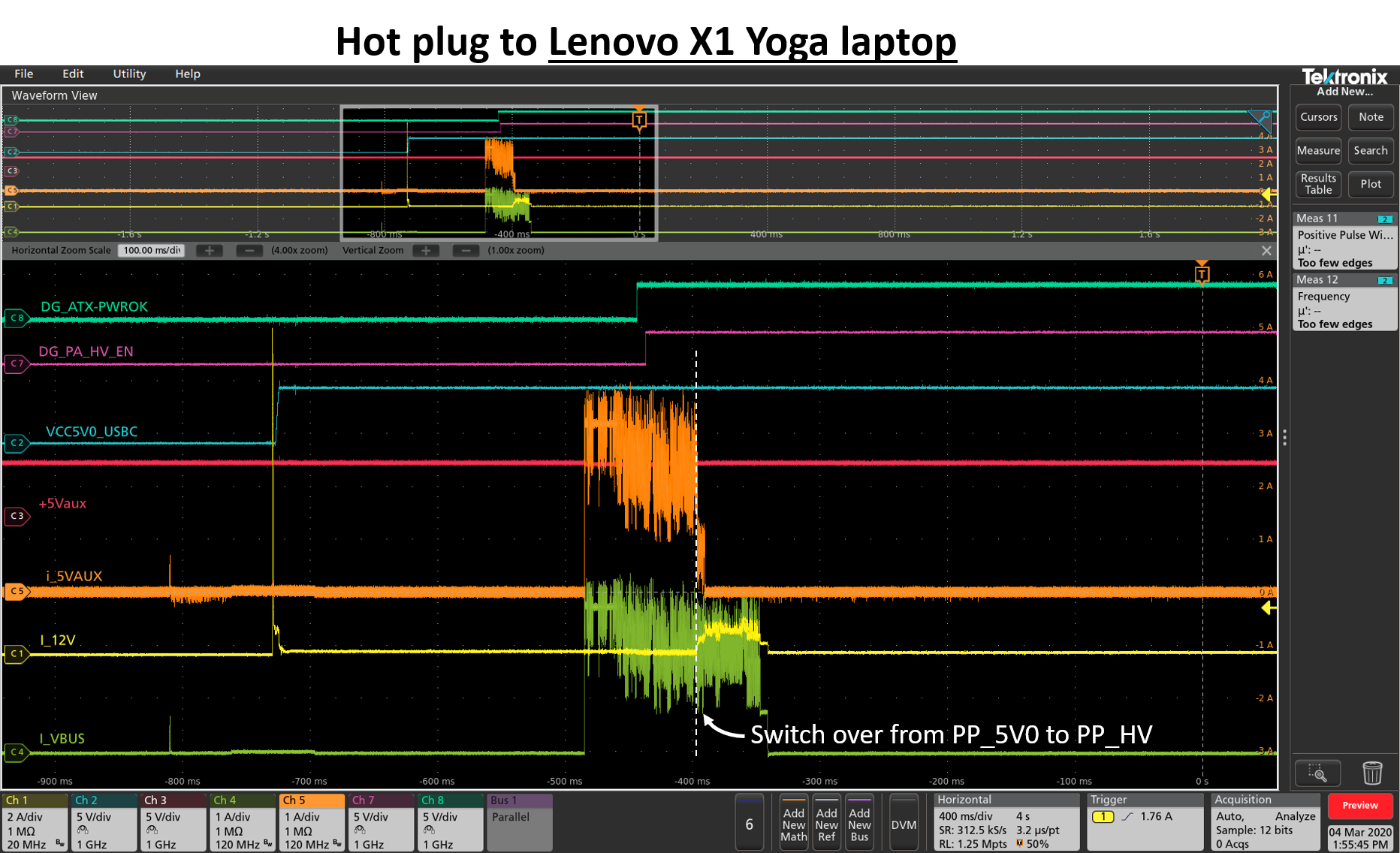
The Lenovo start to draw current before DG_ATX_PWROK asserted. Hence, VBUS is drawing current from PP_5V0 (Aux power) & only switch over to PP_HV (main power) after DG_ATX_PWROK assert. 

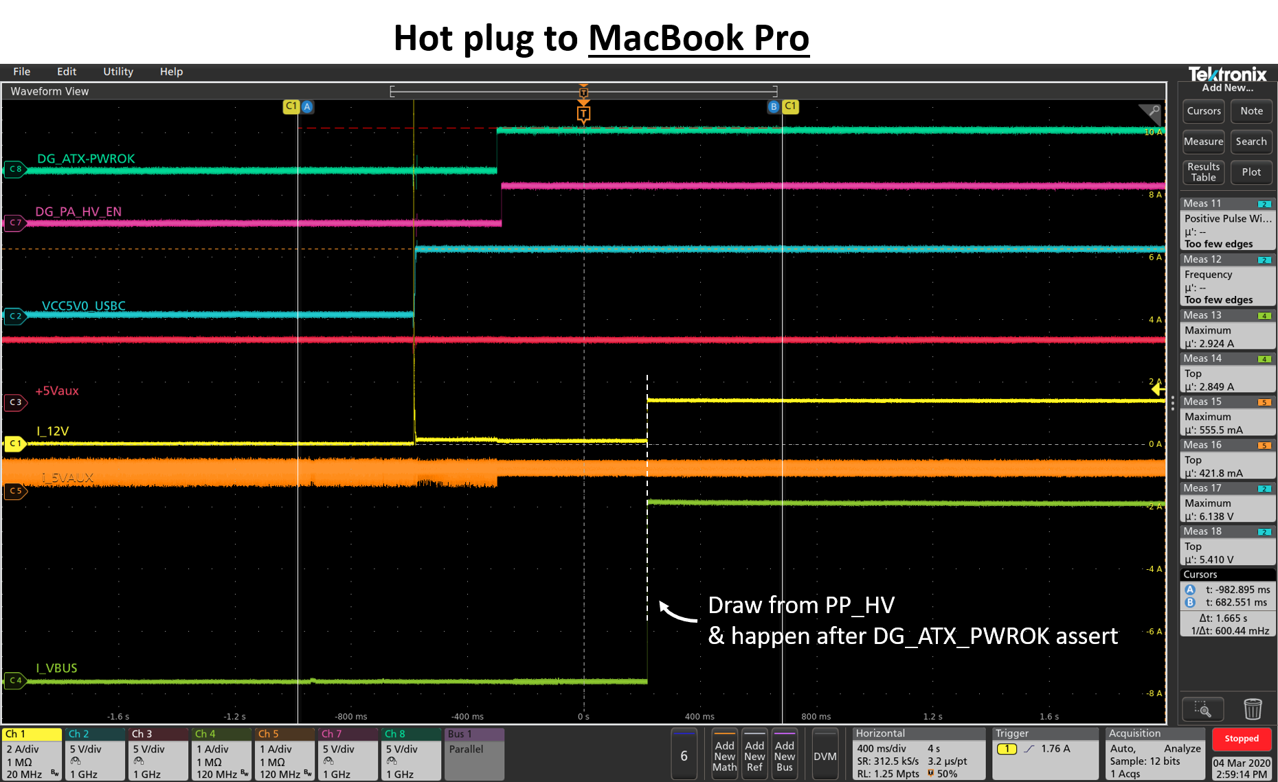
Compare to hotplugging to a Macbook, PD happens after DG_ATX_PWROK. Hence, VBUS is drawing current from the main voltage. (which is correct behaviour)

Question:

1. Please help in explaining the current behaviour seen on the Lenovo laptop.

  • Hi Alice,

    Are you able to record and post  PD traces of the system in both cases?

    Which version of the firmware is being used?

    Regards,

    Scott

  • Hi Scott,

    TI PD FW 4.63. 

    Sure. Please refer to the attached Excel file. PD Trace.xlsx

    Thanks & regards,

    Alice Ng

  • Thanks Alice, can you also post the native format?

    Thanks,

    Scott

  • Hi Scott,

    Not sure what is native format... But I only have this...

    PD trace raw file.zip

    This requires Software from Passmark to open. I have screenshot the content and paste it inside the excel file attached previously.

    Thanks,

    Alice Ng

  • Hi Alice,

    Thank you. The TDC file is from a Total Phase PD Analyzer.  It is easier to see the decoded information in the Total Phase Data Center software.

    The traces show the PD source only offers a 5V 3A contract in all cases. There is no PDO offered > 5V.

    Can you post the TPS65983B project file? Is this the project file modified to support only 5V contracts?

    Thanks,

    Scott 

  • Hi Scott,

    Yes, it is configured to only support 5V@0.9A at PP_5V0 & 5V@3A at PP_HV.  Is the image below contain the info you want? 

    Thanks,

    Alice Ng

  • Hi Alice,

    Is this the only modification to the project? Please post the .pjt file if there are other changes.

    Because only a 5V contract is offered, we should not see any high voltage activity. Only the 5V path should ever be active.

    I remember we made the change earlier for 5V only PDO to support a legacy design. I will check expected operation and reply Monday.

    Regards,

    Scott

  • Hi Scott,

    The other modification I have is setting the IDs & product name. If you would like to have a look, can I have your contact or any alternative way to share the project file privately instead of share it here?

    Thank you.

    Regards,

    Alice Ng

  • Hi Alice,

    Let me investigate just by making the modifications shown in your posted image to start.

    Thank you,

    Scott

  • Hi Alice,

    A few questions about the scope plots that I want to double check for my understanding:

    -Is VCC5V0_USBC the power supply (voltage) input to the TPS6598B PP_5V0 path?

    -Is I_12V the 5V 3A supply (current) input to the TPS65983B PP_HV path?

    -Is I_5Aux the 5V 900mA supply (current) input to the TPS65983B PP_5V0 path?

    -Do you have a plot of V_Vbus?

    Thanks,

    Scott

  • Hi Scott,


    -Is VCC5V0_USBC the power supply (voltage) input to the TPS6598B PP_5V0 path?

    No, VCC5V0_USBC is the voltage input to PP_HV.  +5Vaux (red line) is the voltage input to PP_5V0.

    -Is I_12V the 5V 3A supply (current) input to the TPS65983B PP_HV path?

    Yes

    -Is I_5Aux the 5V 900mA supply (current) input to the TPS65983B PP_5V0 path?

    Yes

    -Do you have a plot of V_Vbus? 

    Yes. Below scope shot is captured during hotplug to the Lenovo laptop. Please refer to the dark blue line.

    Thanks,

    Alice Ng

  • Th-Is VCC5V0_USBC the power supply (voltage) input to the TPS6598B PP_5V0 path?

    No, VCC5V0_USBC is the power supply input to PP_HV. 5Vaux is the power supplt input to PP_5V0.

    -Is I_12V the 5V 3A supply (current) input to the TPS65983B PP_HV path?

    Yes.

    -Is I_5Aux the 5V 900mA supply (current) input to the TPS65983B PP_5V0 path?

    Yes.

    -Do you have a plot of V_Vbus?

    Yes. Please refer scope shot below. V_Vbus coloured as dark blue.

    Thanks,

    Alice Ng

  • Hi Alice,

    Thank you for the update. We are working on an update and I expect to have more information by tomorrow.

    Regards,

    Scott

  • HI Alice,

    I am continuing to research the issue and will update Monday.

    Regards,

    Scott

  • Hi Scott, Alice,

    I hope I can clarify a few things here.

    For the case of the Lenovo notebook the current draw occurs prior to the Source Capabilities for 5V @ 3A and PSRDY which signals to the sink that it is okay to consume up to the negotiated power. Technically a 5V @ 900mA contract is in place when the current is pulled from the notebook. Generally a notebook should set the current limit on the battery charger to the negotiated PD current or Type-C current limit.

    Could the 5V AUX supply this current event?

    Jacob

  • Hi Jacob,

    Our 5V Aux is not able to supply that much of current.

    Are we able to confirm the Lenovo notebook is not setting the current limit on the battery charger to the negotiated PD current limit?

    Thank you.

    Regards,

    Alice Ng

  • Hi Jacob/Scott,

    Are we able to confirm the Lenovo notebook is not setting the current limit on the battery charger to the negotiated PD current limit?

    Thanks,

    Alice Ng

  • Hi Alice,

    I think the behavior is in spec and that this section of the scope plot shows the time between cable attach and before first contract established when Type-C advertised current is in effect.

    Regards,

    Scott

  • Hi Scott,

    To clarify, are you saying that our design with the TI part is functioning correctly and as expected, while the Lenovo device has not been designed to meet the proper specifications?

    Thanks & Regards,

    Alice Ng

  • HI Alice,

    I believe the scope trace shows current draw from the 5v power path under a Type-C implicit contract with the current limit advertised by the source at connection time. This contract is in place until the first PD contract is negotiated. The Notebook is allowed to draw current when the implicit contract is active up to the current limit so I think we are only seeing allowed behavior.

    Regards,
    Scott

  • Hi Scott,

    To make sure we're on the same page,

    If I'm understanding the terms correctly, the implicit contract for our current use case should be at 5V/0.9A. In which case the notebook should be allowed to draw current up to 0.9A until the next PD contact is negotiated. But is the understanding here that the notebook is using this implicit contract to draw 3A during the 5V/0.9 implicit contract?

    Or are you referring to the contract being at 5V/3A and the notebook being allowed to draw that current? If that's the case, shouldn't the TI PD controller be gating the draw until the switch over from Aux power to main power?
    Regards,
    Alice Ng
  • HI Alice,

    I am referring to "USB Type-C VBUS Current Detection and Usage" or an implicit contract. This is the current level permitted before a USB PD Contract is negotiated and agreed on.

    The default current advertisement for the Apex ATX project is 3A. This is displayed to the Sink device by the strength of Rp.

    This limit is separate from the PD contracts we've discussed.

    Regards,

    Scott

  • Hi Scott,

    Thanks for the explanation. To verify my understanding on your reply... 

    This implicit contract is enacted before the PD negotiation (5V/0.9A and then 5V/3A) that we set in our FW.
    Plus, the default current advertised in the Apex ATX project is 3A.
    Hence, Lenovo notebook draws 3 A due to implicit contract occurs.

    Questions:

    1. If that's the case, would I be right in saying that there should be a quick negotiation to establish the 5V/0.9A?
    2. Why this doesn't occur when I use another laptop (e.g. Macbook, Dell)
    3. Is there a way to change the current limit set in implicit contact for the Apex Creek ATX? Its set within the FW?


    Thank you.

    Regards,
    Alice Ng

  • HI Alice,

    I need to check into your questions and will have a reply by Monday.

    Regards,

    Scott

  • HI Alice,

    I can answer questions 1 and 3:

    Yes, the implicit contract is active from first attach, when Sink reads Rp and the Source supplies Vbus to the end of the first PD contract negotiation with PD Messages Accept and PSReady.

    The current TPS65983B Apex Creek project is set to 3V Type-C current advertisement. This is controlled by the TBT reference design..

    Regards,

    Scott

  • Hi Scott,

    Looking back at the PD trace & scope trace, my understanding is...

    After PR_SWAP, implicit contract in place. Hence, VBUS is outputting 5V, 3A. It will remain until explicit contract successful. At this point, VBUS only then change to 5V, 0.9A. Hence, I should expect my scope trace as below:

    1. If this is the case, why the actual scope trace shows nothing after the explicit contract (5V@0.9A) success. Do you have any idea about this?
    2. Can I state during the implicit contract, it will not care whether the voltage source is from PP_5V0 or PP_HV?
    3. Just curious, is the implicit contact's current limit hardcoded in the firmware based on the project we choose? or it is based on the chip (i.e. TPS65983B) we select?

    Thank you.

    Regards,
    Alice Ng

  • Hi Alice, Thank you for the update. I will review and respond on Monday.

    Regards,
    Scott

  • Hi Alice,

    I agree with the general outline in your post. I would like to see CC communication on the same plot as VBus and the supply currents.. It would be easier to align the time line of communication events.

    The device will open the 5v power path for the implicit contract. This is also the contract that will stay in place for a non-PD Type-C device.

    Type-C Current Limits are defined in the device firmware. In the case of TPS5983B, they are set in each reference design project.

    Regards,

    Scott

  • Hi Scott, 

    Thank you for your clarification & suggestion. 


    I would like to see CC communication on the same plot as VBus and the supply currents.

    Do you mean to have a scope trace that contains Voltage of CC line, VBUS current, supply current?


    It would be easier to align the timeline of communication events.

    By probing CC line voltage, I able to identify the power role swap event from the scope trace. This helps to align the timeline from PD trace & the timeline from scope trace. Is my understanding correct? 

    I have difficulty to probe the signal now. But can you share with me what is the expected scope trace behavior to identify the power role swap? 

    Thank you.

    Regards,

    Alice Ng

  • Hi Scott, 

    Do you have the answer for the question on my previous reply?

    Thank you.

    Regards,

    Alice Ng

  • HI Alice,

    Yes, I was thinking about a scope trace adding the CC lines to check for connection status and to help with timing.

    I will contact you about an idea for a firmware test.

    Regards,

    Scott

  • Hi ,

    We captured the PD & scope trace & email it to you on 27th April. 

    From the scope shot, there is no current draw on VBUS. Can you please guide me, is this behavior expected?

    Thank you.

    Regards,

    Alice Ng

  • Hi Alice,

    I understand the test firmware did not work out. For this device further debug needs to work from released firmware. For now I am working with our development team for feedback.

    Regards,

    Scott