This thread has been locked.

If you have a related question, please click the "Ask a related question" button in the top right corner. The newly created question will be automatically linked to this question.

TUSB216: Asking for the design on TUSB216 EVM eye testing

Part Number: TUSB216
Other Parts Discussed in Thread: TUSB217, TUSB212

Hi Team,

Customer is designing TUSB216 and test the eye diagram on EVM

Would you please provide comment for the following questions?

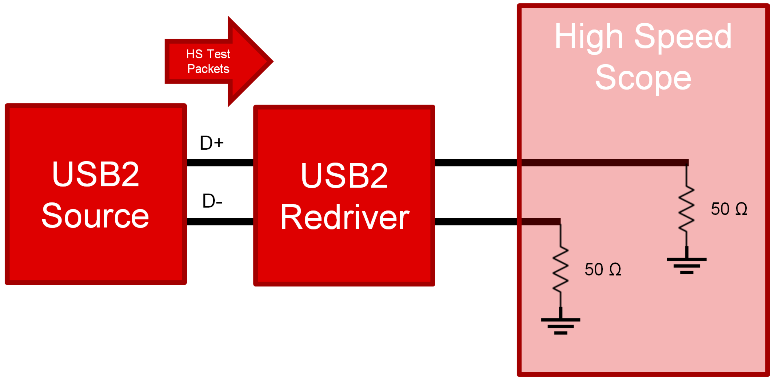
Customer used LeCroy and USB2 test fixture to test TUSB216 eye diagram. Sometime TUSB216 EVB can't work well. The different test procedure has different result.


Test procedure A :

1. Plug a USB2 mass storage device to EVB typeA female port. 

2. The USB2 test fixture switch is at initial mode.

3. Plug EVB to test fixture device connector.

4. Use Host test PC to enumerate storage device and let the device to send test packet.

5. The USB2 test fixture switch to test mode.


Test procedure B :

1. Plug a USB2 mass storage device to EVB typeA female port. 

2. The USB2 test fixture switch is at test mode.

3. Plug EVB to test fixture device connector.

4. The USB2 test fixture switch to initial mode.

5. Use Host test PC to enumerate storage device and let the device to send test packet.

6. The USB2 test fixture switch to test mode.


    When customer used procedure A  to test eye diagram, the TUSB216 EVB always can't work.

The eye waveform can't see any gain. But when customer used procedure B to test, the TUSB216 EVB can work well. And we can see eye diagram has improve. Why has these different result? The user normal scenario should be similar to procedure A. It confuse me that when I use EVB with normal USB device, the EVB can work well or not. No matter the EQ gain setting to any level, the situation are all the same.


BR,

SHH


  • Hi SHH,

    What is the test fixture being used? It seems that in procedure B, TUSB216 seems the termination required to enter test mode and them stay in test mode when the signal is measured. Perhaps in procedure A TUSB216 does not see HS termination for long enough to enter test mode. What is the initial mode of the test fixture that you mentioned?

  • Hi Malik,

    About the test fixture initial mode that let host pc can connect to test device and usb USB IF tool " USBHSETT " to make device sent test package.

    This is the same as 3rd party lab to do USB2 compliance test.

        The test fixture is used for USB2 high speed signal test. This fixture is certification by  USB association.

    BR,

    SHH

  • Hi SHH,

    You should leave the test PC connected to the HS scope with 50 Ohm termination. I believe when the test fixture is in INIT it is connected to a USB device. USB devices will not turn on high speed termination when Host is in test mode due to lack of HS enumeration. 

  • Hi Malik,

    Would you please draw a draft to show how to connect the 50ohm termination?

    BR,

    SHH

  • Hi SHH,

    That 50 ohm termination should be provided by the High Speed Scope. See attached image for reference. 

  • Hi Malik,

         Yesterday customer checked this issue. The status is the same. customer followed the datasheet procedure to test, the TI EVB TUSB216 still can't work.

    If we want TUSB216 work normally, the fixture must be set to TEST mode when the TI EVB is inserted into the test fixture.

    I also try another condition, the procedure is :

    1. Connect as Host PC -> Test fixture(INIT mode) -> TI EVB -> Mass memory storage device.

    2. Check host pc can see the data in memory storage device data.

    3. Host PC turn on the USB test tool.

    4.  Host PC use USB test tool to control memory storage device, and let the device to sent test package.

    5. Test fixture set to Test mode.

    6. Scope test the USB eye waveform.

    Even customer used this procedure, the TI EVB TUSB216 still can't output the gain.

         customer is worry about putting TUSB216 in our circuit, when the user uses it normally, TUSB216 cannot send out gain normally.

    Please help to check. Thanks.

    BR,

    SHH

  • Closing thread, discussion moved to internal email. 

  • Hi Malik,

    My name is Pal Edwards and I work for Logitech in the Test Lab..

    I am having the same problem with the TUSB216 as this thread indicates… If I didn’t know better the source of the issue are my colleges in Taiwan.

    It seems that the 216 never configures to resistor setup we use… We can set the 216 into the Test Packet mode but for some reason without going through the B Process the resistor settings are not enabled…

    The outputs from CD and ENS are also not seemingly correct…

    I have also used the TUSB217EVK and found that I don’t need to do Process B to get the signal improvement using the USB-IF Device Test Fixture BUT I can’t plug a device into the EVK and see any signal improvement from the original device output… I can see signal improvement when I run the Test Packet command from HCI HSETT through the Test Fixture…

    So is it possible that the 216 and 217 when connected if they don’t immediately see a HS

    (USB) device on either end their drop permanently into the Low Speed mode and disable the signal conditioning?

  • Hi Pal,

    TUSB216 and TUSB217 should enter test mode when they see ~45-50 ohm termination on DM with no HS data on the bus. In addition, in order to update the settings used by TUSB216 and TUSB217 a reset must occur. Both devices only "look" at the resistor settings ar power-on reset. 

    What is the state of CD and ENA_HS that you see? Can you describe your test setup? Do you have any scope capture of what you are seeing?

    Just to confirm procedure B is the below correct? This sequence is not required to enter test mode. Using this procedure you are using the mux on the test fixture to connect do the following, USB device (Compliance mode enabled) --> TUSB21x --> High speed scope, correct?

    Test procedure B :

    1. Plug a USB2 mass storage device to EVB typeA female port. 

    2. The USB2 test fixture switch is at test mode.

    3. Plug EVB to test fixture device connector.

    4. The USB2 test fixture switch to initial mode.

    5. Use Host test PC to enumerate storage device and let the device to send test packet.

    6. The USB2 test fixture switch to test mode.

  • Hi Malik,

    Pictures in attached Response1.doc file

    I did some more testing with the EVKs yesterday… And I have another issue… Let me start with this then roll into your questions…
    I started with the 212 because that is what the EEs initially started looking at in the design…

    Setup:

    The following is the waveform that I get when the Compliance Test is run per the correct sequence…

    When I press the Reset Button on the EVK the waveform outputted from then on is the following:

    Notice the drop in amplitude…And it stays at this amplitude until I go back and restart the testing….

    Why doesn’t after releasing the RESET button the amplitude of the signal go back to previous Testing levels… Because the datasheet says:

    “In order for the TUSB212 to recognize any change to the AC or DC boost settings, the RSTN pin must be toggled. This is because the EQ and DC_BOOST pins are latched on power up and the pins are ignored thereafter.”

    Your testing procedure for determining what setting to use in the datasheet give no indication that you need to restart the test between each setting change if you use the RESET line…Response1.docx

  • Hi Paul,

    I can understand the confusion. TUSB21x will only enter compliance made when there is not signal present at power-on reset (POR). So if you press the reset button and HS data is still preset boosting will not be enabled. However if you disconnect the EVM, this gives time for TUSB21x to enter compliance mode and enable boosting once signal is present.The datasheet is only generally referring to updating the EQ settings of the device in GPIO mode.

  • So if I were to go into Test Mode, then Reset the 212, then used the HCI HSETT App to command a Stop Test Packet, then Commanded a Test Packet I should get the same boosted signal?

    If that's the case we are ok unless the power is interrupted during a data stream...

    Now back to the other issue... Any ideas why the Process  A would put the 212 into a shutdown mode?

  • Hi Paul,

    I would recommend you command Stop Test packet then reset TUSB212 and then restart test packets but that method should also work and yes if the power is interrupted then the boosting will disable. 

    From the steps listed it seems that the redriver has disabled boosting due to USB device entry into test mode. USB bus is idle for a "long" time when USB device enters test mode (timing can change depending on the device) but does not occur after TUSB21x POR. TUSB21x cannot assume this is test mode and disables the boost.